Model a villa ground floor roof beam and slab framing plan
- Software
- Autodesk Revit
- Platform
- Windows
- Length
- 10 h 58 min
- Resolution
- 1920 × 1080
- Output
- RVT
Windows
Task
Build a structural model of the ground floor roof framing for an east-facing residential villa (East Villa, 222 sq. yd), following the supplied dimensioned diagrams diagram_01.png, diagram_01_detail01.png and diagram_01_detail02.png. Work in imperial units (feet and inches).
Create a level for the ground floor roof and model the reinforced concrete beam grid with columns at the beam intersections shown. Every beam is 9" wide. Use beam types for the three depths that appear: 9"x18", 9"x24" and 9"x30". Identify each beam by its mark as shown on the plan:
- B1 (9"x24") along the north edge
- B6 along the west edge: 9"x24" in the north bay and 9"x18" in the bays below
- B11 / BR11 (9"x30") along the east edge
- B5 and BR5 (9"x30") along the south edge
- B4 internal east-west beams: 9"x24" in the west portion and 9"x18" in the east portion
- B2 (9"x18") south of the staircase
- B3 (9"x18") in the west bay
- B7, B8, B9, B10 and BR10 (9"x18") as internal north-south beams
Set out the bays to the clear dimensions shown. The northern bays are 13'-2", 4'-7" and 12'-8" wide. The central row is 13'-2" and 18' wide. The southern bays are 5'-6", 10'-4" and 14'-7" wide. Vertical spans include 18'-3", 7'-11", 9'-8", 10'-5", 16'-6", 12'-7" and 15'-1".
Model the roof slab over the framing with these features:
- A staircase opening in the north-east bay, approximately 12'-8" by 10'-5".
- Two 12" sunken slab areas: one in the 4'-7" bay in the north and one in the 5'-6" bay in the south-west.
- Slab projections at beam top along the south edge: a 5" projection over the 18'-6" western length, and a 12" projection over the 16'-4" eastern length that returns up the east side for 15'-1".
Tag the beams with their marks and sizes and dimension the bays in the roof framing plan view. Include North, South, East and West elevation markers around the plan.
ReferenceSheet 1
Loading the drawing
Rubrics15
- R1
The model shall contain structural framing beams 9" wide in depths of 18", 24" and 30".
- R2
The model shall include a 9"x24" beam marked B1 along the north edge of the framing.
- R3
The model shall include 9"x30" beams along the east edge marked B11/BR11 and along the south edge marked B5 and BR5.
- R4
The model shall include a beam marked B4 running east-west, 9"x24" in its western portion and 9"x18" in its eastern portion.
- R5
The model shall include 9"x18" beams marked B2, B3, B7, B8, B9, B10 and BR10.
- R6
The model shall include a beam line marked B6 along the west edge, 9"x24" in the north bay and 9"x18" in the remaining bays.
- R7
The model shall include columns at the beam intersections shown on the plan.
- R8
The model shall include a roof slab with an opening at the staircase bay of approximately 12'-8" by 10'-5".
- R9
The model shall represent two sunken slab areas depressed 12", in the 4'-7" bay and in the 5'-6" bay.
- R10
The model shall include slab projections along the south edge of 5" (over 18'-6") and 12" (over 16'-4", returning 15'-1" up the east side).
- R11
The model shall set out the bays with clear dimensions including 13'-2", 4'-7", 12'-8", 18', 10'-4", 14'-7" and 18'-3".
- R12
The drawing shall tag beams with their marks and sizes, such as B5(9"X30").
- R13
The drawing shall dimension the bay spans in the framing plan view.
- R14
The model shall be in imperial units, with a level for the ground floor roof.
- R15
The drawing shall show North, South, East and West elevation markers on the plan.
Gold outputg_1_villaRVT
1 of 13Loading
Drag to turn, then scroll to zoom
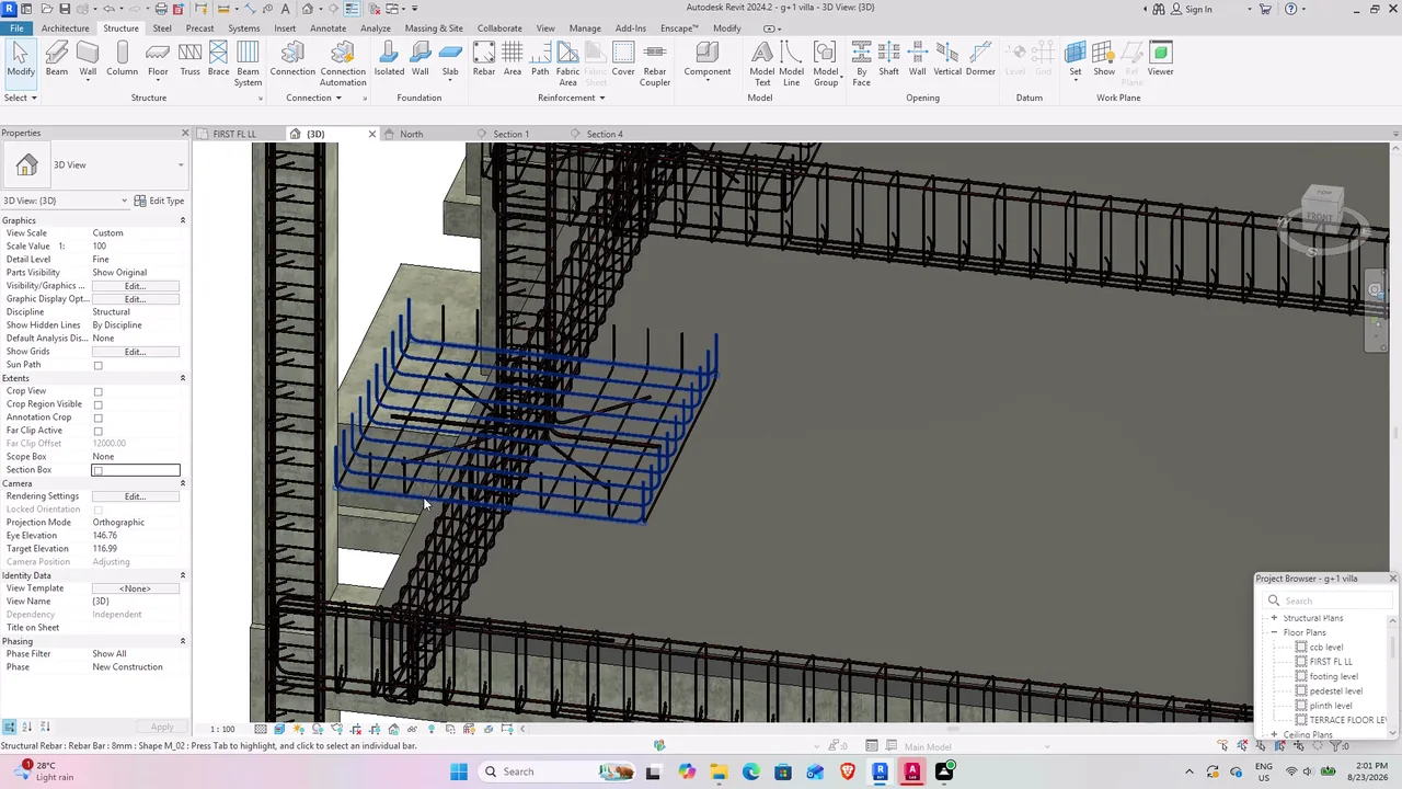
Build a structural model of the ground floor roof framing for an east-facing residential villa (East Villa, 222 sq.
Inspect and edit the g+1 villa’s reinforced-concrete structural model in Revit, configuring rebar shapes, sizes, spacing, covers, sketches, and visibility across plans, sections, elevations, and 3D views. Cross-check the modeled reinforcement and framing against the related AutoCAD duplex structural drawings, beam details, roof layouts, stairs, and elevations, with a PDF export initiated near the end.
Task set
task.pdfThe task: statement, rubrics and every drawing sheet1 MB↗task_desc.jsonThe task as data: statement, input files and deliverables3 KB↗rubrics.jsonThe rubrics as data2 KB↗references.zipThe drawing sheets and close-ups the task works from14 MB↓gold.zipThe finished files: native and neutral exports9 MB↓