Model a steel stair and platform weldment
- Software
- SOLIDWORKS
- Platform
- Windows
- Length
- 2 h 17 min
- Resolution
- 1920 × 1080
- Output
- SLDPRT, STEP, X_T
Windows
Task
Model a steel access platform with a stair at each end as a single multibody weldment part. Work in millimetres and set the material to Steel. Build it to the supplied dimensioned diagrams diagram_01.png and diagram_01_detail01.png through diagram_01_detail04.png.
Platform: lay out a rectangular frame sketch 2500 mm long by 800 mm wide. Place C channel 80 x 8 structural members on the four perimeter members and on two internal cross members. Cover the frame with a 20 mm thick deck plate measuring 2500 x 800 mm on top.
Support: four C channel 80 x 8 legs, each 750 mm long, run from the top of the frame down to floor level. The floor is 750 mm below the frame top, or 670 mm below the underside of the 80 mm deep frame. The legs sit in pairs at roughly ±700 mm from the platform centre, giving the 1280 mm leg spacing shown in plan. Trim the legs and frame where they meet.
Stairs: at each end, a pair of C channel 80 x 8 stringers descends at 45° to the floor. Cut the stringer ends so they finish level at the floor and at the platform. The ends of the stringers span 4000 mm overall.
Treads: each stair has three treads, giving 6 treads and 12 brackets in total.
- Each tread is a 15 mm plate, 200 mm deep and about 670 mm wide.
- Each tread is carried on two 200 x 50 mm bracket plates, one on each stringer.
Handrails: model the handrails as Pipe 33.7 x 4.0 structural members along both long sides and down both stairs. Use a top rail at 620 mm and a mid rail at 270 mm above the frame top, with vertical posts. Trim the handrail members at their joints.
Mirroring: model one side or one stair of each group, then create the rest with mirror features. This applies to the legs and stringers, tread brackets, tread plates and handrails.
Base plates: add 30 mm thick base plates under every foot, 8 in total:
- 200 x 80 mm under the stringer feet
- 150 x 80 mm under the legs
Overall envelope: about 4086.87 mm long, 1416.85 mm high (base plate underside to top of handrail) and 936 mm wide across the base plates.
Model structure:
- Use descriptive feature names, for example Platform Frame Layout, Leg and Stringer Layout, Tread Brackets, Tread Plates 15mm, Deck Plate 20mm, Handrail Layout, Stringer End Cut and Base Plates 30mm.
- Organise the bodies into cut-list folders by profile.
- Keep the weldment's As Machined and As Welded configurations.
- Add the custom properties Description, PartNo and Material.
ReferenceSheet 1
Loading the drawing
Rubrics15
- R1
The model shall be a single multibody weldment part in millimetres with material Steel.
- R2
The model shall have an overall bounding box of approximately 4086.87 x 1416.85 x 936 mm.
- R3
The model shall include a platform frame of C channel 80 x 8 members laid out on a 2500 x 800 mm rectangle with two internal cross members.
- R4
The model shall include a 20 mm thick deck plate measuring 2500 x 800 mm on top of the platform frame.
- R5
The model shall include four C channel 80 x 8 legs, each 750 mm long, running from the frame top down to floor level.
- R6
The model shall include four C channel 80 x 8 stringers inclined at 45°, two at each end, with end cuts spanning 4000 mm overall.
- R7
The model shall include six 15 mm thick tread plates 200 mm deep, three per stair.
- R8
The model shall include twelve tread bracket plates of 200 x 50 mm supporting the treads.
- R9
The model shall include handrails built from Pipe 33.7 x 4.0 members on both long sides and both stairs, with a top rail 620 mm above the frame top.
- R10
The model shall include eight 30 mm thick base plates under the stringer feet and legs.
- R11
The model shall have descriptively named features including a platform frame layout sketch, tread, deck plate, handrail, stringer end cut and base plate features.
- R12
The model shall use mirror features to replicate the legs and stringers, tread brackets, tread plates and handrails.
- R13
The model shall organise its bodies into cut-list folders for the C channel 80 x 8 and Pipe 33.7 x 4.0 members.
- R14
The model shall contain the As Machined and As Welded configurations.
- R15
The model shall carry the custom properties Description, PartNo and Material.
Gold outputweldments_Steel_StairSLDPRT, STEP, X_T
Loading
Drag to turn, then scroll to zoom
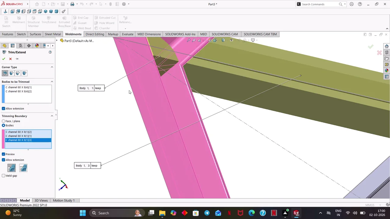
Model a steel access platform with a stair at each end as a single multibody weldment part.
Created and refined a SOLIDWORKS steel stair-weldment part, including structural members, trims, mirrors, sketches, brackets, stairs, railings, and extrusions. Saved the completed model as “weldments Steel Stair” and printed it to a PDF named “Weldments Steel Stair.”
Task set
task.pdfThe task: statement, rubrics and every drawing sheet13 MB↗task_desc.jsonThe task as data: statement, input files and deliverables4 KB↗rubrics.jsonThe rubrics as data2 KB↗references.zipThe drawing sheets and close-ups the task works from11 MB↓gold.zipThe finished files: native and neutral exports2 MB↓