Model a four-cylinder engine crankshaft, piston and connecting rod assembly
- Software
- CATIA V5
- Platform
- Windows
- Length
- 5 h 26 min
- Resolution
- 1920 × 1080
- Output
- CATPART, CATPRODUCT
Windows
Task
Model the reciprocating crank train of an inline four-cylinder engine as a set of solid parts in millimetres, then assemble them into a product. Work from the supplied dimensioned diagrams: diagram_01.png, diagram_01_sheet2.png to diagram_01_sheet6.png and their detail images.
Create six parts, each named after the component:
1. PISTON: outside diameter Ø85, overall height 90, domed crown of R120.
- Three ring grooves, 4.3 wide, with a groove-root diameter of Ø79.
- Inner cavity Ø76, 85 deep from the open end.
- Ø33.8 transverse piston-pin bore, with skirt cut-outs 27 high at the pin bosses.
- Section A-A detail: R40 underside relief, R10 transitions, and widths of 38 and 50 across the pin bosses.
2. CONNECTING_ROD: small end of Ø45 outside with a Ø33.8 pin bore. Big-end half-bore of R27 / R36, rod width 38 at the big end, 201.2 between the pin and crankpin centres, and two Ø9 bolt holes at 76 centres.
3. CONNECTING_ROD_CAP: the mating half-bearing cap.
- 94 wide, 60 high and 38 thick.
- Half-bore R27 inside, R36 outside.
- R10 corner blends and 27.5 / 22.53 chamfer geometry.
- Two Ø9 bolt holes in R9 bosses at 76 centres.
4. CRANKSHAFT: a single shaft.
- Ø32 nose, 80 long.
- Ø72 main journals, 38 long.
- Ø54 crankpins, 46 long, offset 44 from the shaft axis.
- Webs 15 thick with an R80 / R36 profile and a 33° taper.
- Rear flange Ø144, 10 thick, carrying 8 holes of Ø10 on a Ø100 bolt circle.
5. PISTON_PIN: a Ø33.8 pin, 82 long.
6. PISTON_RING: a flat ring, Ø85 outside and Ø79 inside, 4.3 thick.
Build a sub-product named MINI_ASSEMBLY for one cylinder. It holds one piston, three piston rings seated in the grooves, one piston pin through the piston and the rod small end, one connecting rod, and one connecting rod cap closed on the rod big end.
Build the top-level product 4_CYLINDER_ENGINE_ASSEMBLY. It contains the crankshaft and four MINI_ASSEMBLY instances, one per crankpin, so that the big ends sit concentric on the crankpins. The pistons stand at the staggered heights set by the crank throws, as shown in the front, top and isometric views at 1:5.
The bill of materials must resolve to:
- PISTON ×4
- CONNECTING ROD ×4
- CRANKSHAFT ×1
- CONNECTING ROD CAP ×4
- PISTON RING ×12
- PISTON PIN ×4
Save each part as its own CATPart and each product as a CATProduct.
ReferenceSheet 1, page 1
1 of 6Loading the drawing
Rubrics18
- R1
The model shall include a PISTON part with outside diameter 85 and overall height 90.
- R2
The PISTON shall have three ring grooves 4.3 wide with a root diameter of 79.
- R3
The PISTON shall have a transverse pin bore of diameter 33.8 and an internal cavity of diameter 76.
- R4
The PISTON crown shall be domed with radius 120.
- R5
The model shall include a CRANKSHAFT part with a rear flange of diameter 144 and thickness 10.
- R6
The CRANKSHAFT flange shall carry 8 holes of diameter 10 on a 100 diameter bolt circle.
- R7
The CRANKSHAFT shall have main journals of diameter 72 and a front nose of diameter 32 and length 80.
- R8
The CRANKSHAFT shall have four crankpins of diameter 54 offset 44 from the main axis, separated by webs 15 thick.
- R9
The model shall include a CONNECTING_ROD_CAP part 94 wide, 60 high and 38 thick, with a half-bore of radius 27.
- R10
The CONNECTING_ROD_CAP shall have two bolt holes of diameter 9 at 76 centres.
- R11
The model shall include a CONNECTING_ROD part whose small-end bore is diameter 33.8.
- R12
The model shall include a PISTON_PIN part of diameter 33.8 and length 82.
- R13
The model shall include a PISTON_RING part with outside diameter 85, inside diameter 79 and thickness 4.3.
- R14
The model shall position each connecting rod big end concentric with a crankpin, with the cap closed around it.
- R15
The model shall seat each piston pin through its piston and the connecting rod small end.
- R16
The model shall contain a MINI_ASSEMBLY product grouping one piston, three piston rings, one piston pin, one connecting rod and one connecting rod cap.
- R17
The model shall contain a top-level 4_CYLINDER_ENGINE_ASSEMBLY product holding one CRANKSHAFT and four MINI_ASSEMBLY instances.
- R18
The model's product structure shall total 4 pistons, 4 connecting rods, 1 crankshaft, 4 connecting rod caps, 12 piston rings and 4 piston pins.
Gold output4_CYLINDER_ENGINE_ASSEMBLYCATPRODUCT
1 of 8Loading
Drag to turn, then scroll to zoom
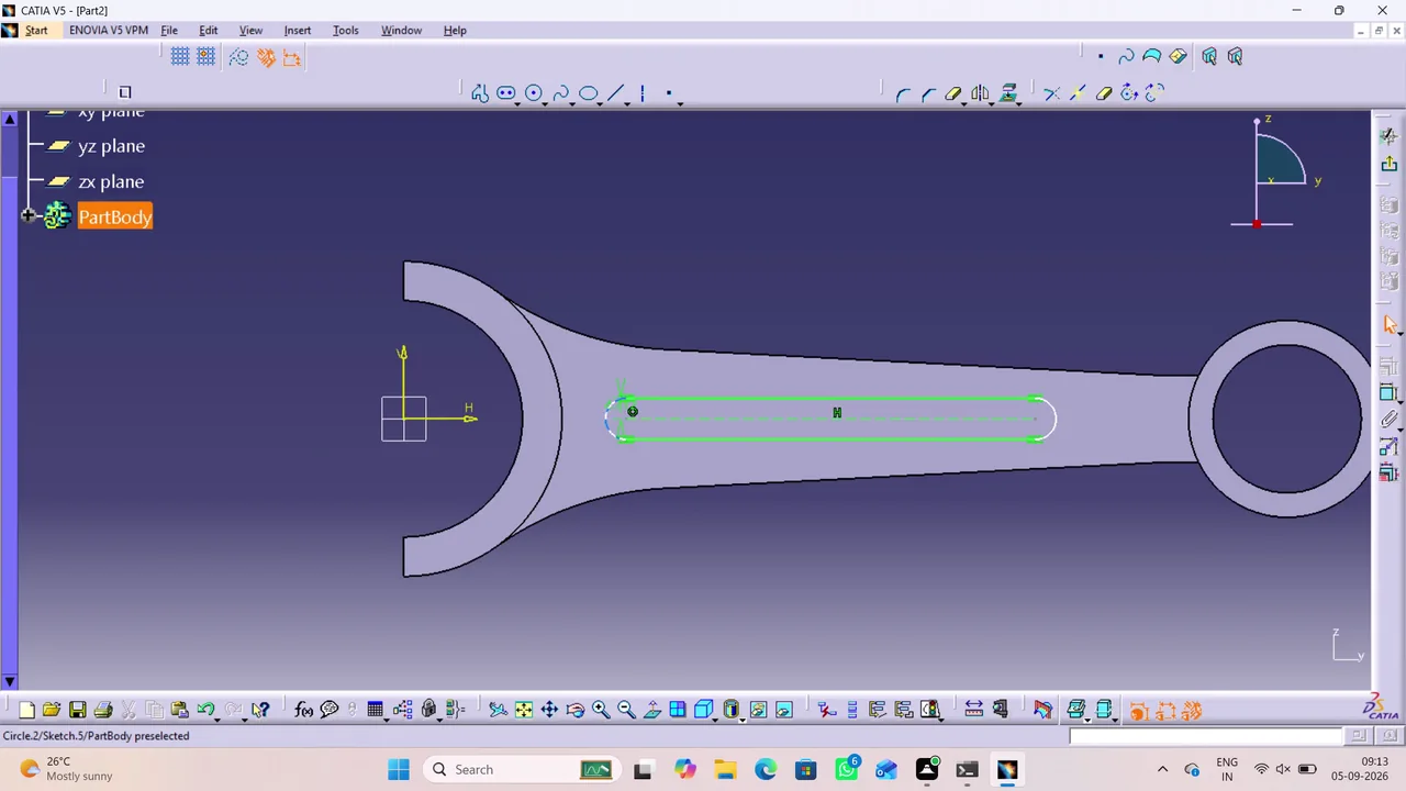
Model the reciprocating crank train of an inline four-cylinder engine as a set of solid parts in millimetres, then assemble them into a product.
Create and document a detailed four-cylinder engine assembly in CATIA V5 by modeling its components, assembling and constraining them, applying materials, and producing annotated technical drawings and PDF exports for the piston, connecting rod, crankshaft, connecting rod cap, piston pin/ring, and overall assembly.
Task set
task.pdfThe task: statement, rubrics and every drawing sheet9 MB↗task_desc.jsonThe task as data: statement, input files and deliverables7 KB↗rubrics.jsonThe rubrics as data3 KB↗references.zipThe drawing sheets and close-ups the task works from10 MB↓gold.zipThe finished files: native and neutral exports1 MB↓