Model a wheel support bracket assembly and its components
- Software
- PTC Creo
- Platform
- Windows
- Length
- 1 h 45 min
- Resolution
- 1920 × 1200
- Output
- PRT, ASM
Windows
Task
Model every component of a wheel support bracket and assemble them as shown on the supplied dimensioned diagrams (diagram_01.png and its details diagram_01_detail01.png through diagram_01_detail06.png). Work in millimetres. Create each component as its own part file, then build a top-level assembly named wheelsupportass.
Parts and key dimensions:
- Base (base): rectangular plate 115 × 40 × 5. It has four through holes of R2.5 on a 65 × 20 rectangular pattern. The first hole sits 25 from the short end and 10 from the long edge.
- Support (supports): bent L-shaped bracket with a 40-high upright and a 40-wide flange, and an inside bend radius as shown. The flange carries two R2.5 holes spaced 20 apart, located 10 and 15 from the edges, matching the base hole pattern. The upright carries the hole for the shoulder screw. Two supports face each other across the wheel.
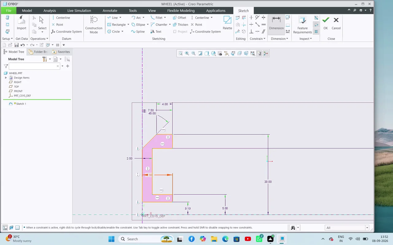
- Wheel (wheel): outer radius R20 with a stepped face at R16.5. The overall width is 15, with a central 90° V-groove around the rim. The hub is R5 with an R3.13 bore.
- Shoulder screw (shoulderscrew2): overall length 37. It has a Ø10 × 4 head, a Ø6.25 shoulder 27 long and a Ø4 threaded end.
- Bushing (bushing): R5 outside, R3.13 bore, 5 long.
- Washer (washer): R6 outside, R3.13 inside, 1 thick.
- Nut (nut): hexagon 10 across corners, 5 thick, with an R2 bore and chamfered faces.
- Bolt (screw): hex-head bolt, as dimensioned on the sheet, used to fasten the supports to the base.
Assembly: place the base as the foundation. Mount the two supports on its top face with their flanges aligned to the base holes, and fasten each flange with hex bolts through the matching holes. Fit the wheel between the two uprights on the shoulder screw, which passes through the uprights and the wheel bore. Use the bushing and washer on the shaft and the nut on the threaded end. Constrain all parts so the axes and hole patterns align without interference.
ReferenceSheet 1
Loading the drawing
Rubrics16
- R1
The base part shall be a 115 × 40 × 5 rectangular plate.
- R2
The base shall contain four R2.5 through holes spaced 65 by 20, with the first hole located 25 and 10 from the plate edges.
- R3
The wheel part shall have an outer radius of R20 and an overall width of 15.
- R4
The wheel shall have a central V-groove with an included angle of 90°.
- R5
The wheel shall have a hub of R5 with a bore of R3.13.
- R6
The shoulder screw part shall have an overall length of 37 with a 27-long Ø6.25 shoulder.
- R7
The shoulder screw shall have a Ø10 head 4 long and a Ø4 end section.
- R8
The bushing part shall be a sleeve with R5 outside radius, R3.13 bore and length 5.
- R9
The washer part shall have an outside radius of R6, an inside radius of R3.13 and a thickness of 1.
- R10
The nut part shall be a hexagon 10 across corners, 5 thick, with an R2 bore.
- R11
The support part shall be an L-shaped bent bracket with 40 × 40 legs.
- R12
The support flange shall carry two holes spaced 20 apart, positioned 10 and 15 from the edges.
- R13
The assembly shall contain two support instances mounted on the base, facing each other on either side of the wheel.
- R14
The assembly shall contain hex bolts passing through the support flange holes and the matching base holes.
- R15
The assembly shall locate the wheel coaxially on the shoulder screw between the two support uprights.
- R16
The assembly shall be saved as wheelsupportass, referencing the separate part files base, bushing, nut, screw, shoulderscrew2, supports, washer and wheel.
Gold outputwheelsupportassASM
1 of 9Loading
Drag to turn, then scroll to zoom
Model every component of a wheel support bracket and assemble them as shown on the supplied dimensioned diagrams (diagram_01.png and its details diagram_01_detail01.png through diagram_01_detail06.png).
Built multiple Creo Parametric parts for a wheel-support assembly, assembled and constrained the components, and created a labeled, dimensioned engineering drawing. Exported the completed drawing as a PDF and briefly reviewed the output.
Task set
task.pdfThe task: statement, rubrics and every drawing sheet1 MB↗task_desc.jsonThe task as data: statement, input files and deliverables5 KB↗rubrics.jsonThe rubrics as data2 KB↗references.zipThe drawing sheets and close-ups the task works from1 MB↓gold.zipThe finished files: native and neutral exports465 KB↓