Model a two-stroke engine cylinder block part
- Software
- SOLIDWORKS
- Platform
- Windows
- Length
- 1 h 27 min
- Resolution
- 2560 × 1600
- Output
- SLDPRT, STEP, X_T
Windows
Task
Build a single-part 3D solid model of a model-engine cylinder block (two-stroke engine body) from the supplied dimensioned diagrams: diagram_01.png and its details diagram_01_detail01.png to diagram_01_detail04.png. The diagrams show top, front, right side and isometric views. Work in millimetres.
The block is one solid body with an overall envelope of 131.1 x 108 x 80 mm. It has these elements:
- Crankcase. A revolved crankcase with an internal revolved cavity, an integral side boss and a revolved front housing (R26 / R25 per the right side view).
- Cylinder barrel. An 80 mm square-section barrel with R10 corner fillets and a through cylinder bore of Ø40.
- Cooling fins. Four 2 mm thick cooling fins patterned at 6 mm spacing. Three 2 mm lower side fins, also patterned at 6 mm.
- Head flange. A thin head flange with four head bolt bosses and 4x Ø4 head bolt holes.
- Exhaust stack. A revolved, bored exhaust stack, joined to the crankcase by a 4 mm connecting web and an upper boss of Ø12.
- Mounting lugs. Two 5 mm mounting lugs with mirrored Ø8 mounting holes (R4 on the front view).
- Side tabs. A pair of mirrored 5 mm side tabs, each with an R5 end and a Ø6 hole.
- Blend fillets. Apply blend fillets of R1 to R5 where shown, including R4 crankcase edges, R5 side boss blends and R2 web, bore and cavity blends.
Follow the figured dimensions on the diagrams: 22.1 / 38 / 26 / 45 and 108 (48 / 36.5 / 23.5) in the top view, 80 (26 / 28 / 26) and 131.1 (22.1 / 21.5 / 23.5 / 64) in the front view, and 25 / 56 / 27 in the right side view.
Model it professionally:
- Give every sketch and feature a descriptive name, for example "Crankcase Revolve", "Cylinder Bore Ø40" and "Cooling Fin Pattern 4x6mm".
- Fully define the sketches.
- Use revolves for the rotational features, linear patterns for the fins and mirrors for the symmetric holes and tabs.
- Assign the material Plain Carbon Steel.
- Add these custom properties: Description (a short description of the cylinder block), PartNo = "Engine-Cylinder-Block" and Material = "Plain Carbon Steel".
- Keep a single Default configuration.
ReferenceSheet 1
Loading the drawing
Rubrics16
- R1
The model shall be a single solid body with an overall bounding box of 131.1 x 108 x 80 mm.
- R2
The model shall use millimetres as its unit system.
- R3
The model shall contain a revolved crankcase feature with a revolved-cut internal crankcase cavity.
- R4
The model shall contain a cylinder barrel extruded 80 mm with R10 corner fillets.
- R5
The model shall contain a through cylinder bore of Ø40.
- R6
The model shall contain 2 mm thick cooling fins arranged in a linear pattern of 4 instances at 6 mm spacing.
- R7
The model shall contain 2 mm lower side fins arranged in a linear pattern of 3 instances at 6 mm spacing.
- R8
The model shall contain four Ø4 head bolt holes in head bolt bosses at the cylinder head flange.
- R9
The model shall contain a revolved exhaust stack and a revolved front housing, each with a bore.
- R10
The model shall contain 5 mm mounting lugs with Ø8 mounting holes mirrored about the part's symmetry plane.
- R11
The model shall contain mirrored 5 mm side tabs, each with a Ø6 hole.
- R12
The model shall contain a 4 mm connecting web and a Ø12 upper boss between the crankcase and the exhaust stack.
- R13
The model shall have the material Plain Carbon Steel assigned, giving a mass of approximately 1.10 kg.
- R14
The model shall carry custom properties PartNo = "Engine-Cylinder-Block" and Material = "Plain Carbon Steel", plus a Description property.
- R15
The model shall use descriptive feature names in the feature tree, such as "Crankcase Revolve" and "Cylinder Bore Ø40", rather than default names.
- R16
The model shall contain a configuration named Default.
Gold outputEngine-Cylinder-BlockSLDPRT, STEP, X_T
Loading
Drag to turn, then scroll to zoom
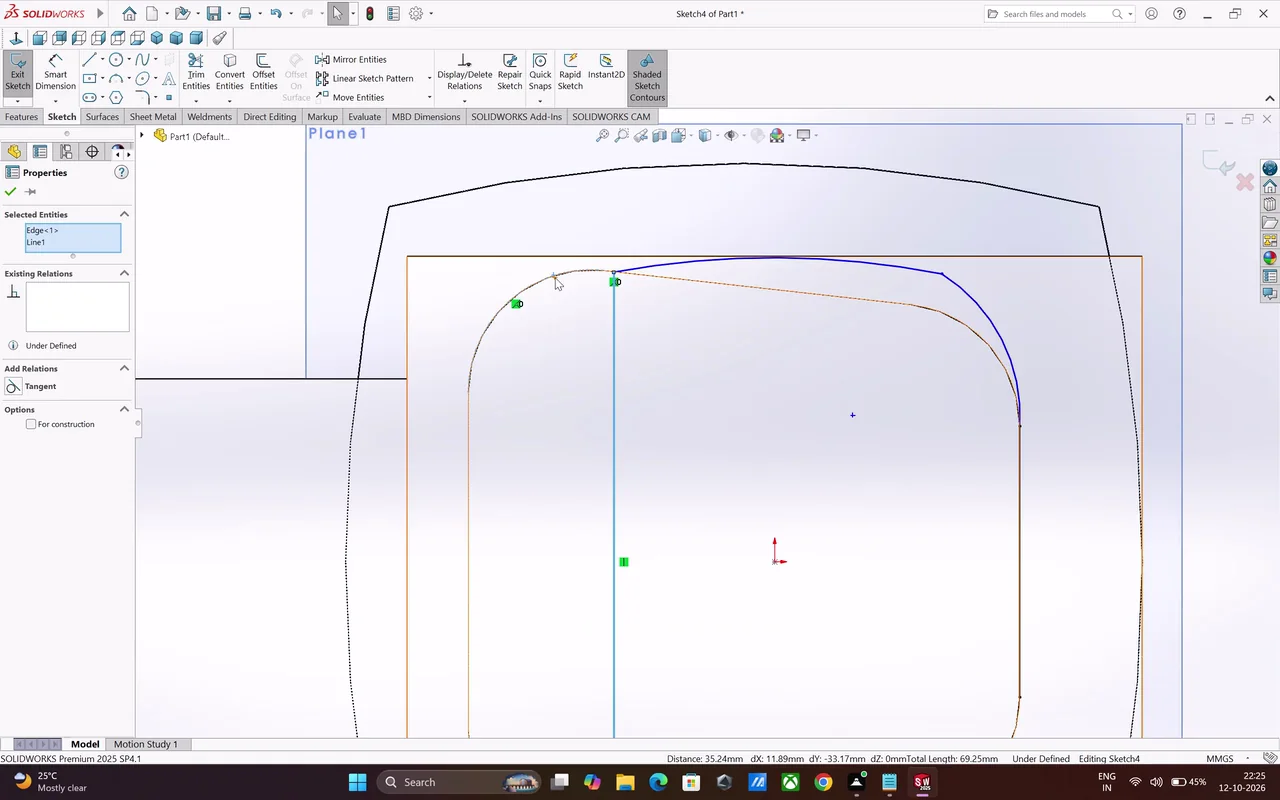
Build a single-part 3D solid model of a model-engine cylinder block (two-stroke engine body) from the supplied dimensioned diagrams: diagram_01.png and its details diagram_01_detail01.png to diagram_01_detail04.png.
Create and iteratively refine a detailed SOLIDWORKS engine-cylinder-block part, adding revolved, extruded, cut, patterned, mirrored, filleted, and reference-geometry features through numerous constrained sketches. Save the finished model as “Engine-Cylinder-Block,” inspect it from multiple angles, and access appearance, document settings, and print/save workflows.
Task set
task.pdfThe task: statement, rubrics and every drawing sheet5 MB↗task_desc.jsonThe task as data: statement, input files and deliverables3 KB↗rubrics.jsonThe rubrics as data2 KB↗references.zipThe drawing sheets and close-ups the task works from5 MB↓gold.zipThe finished files: native and neutral exports2 MB↓