Model a six-blade twisted-tooth pinion shaft with splined end
- Software
- CATIA V5
- Platform
- Windows
- Length
- 2 h 30 min
- Resolution
- 1920 × 1080
- Output
- CATPART, IGS
Windows
Task
Build a single solid part of a spiral-type pinion shaft as shown in the supplied dimensioned diagrams. These are diagram_01.png, the overall sheet with top, front, right side and isometric views, and its enlargements diagram_01_detail01.png to diagram_01_detail04.png. All dimensions are in millimetres. The views are in third-angle projection.
The part is a straight shaft with one rotational axis. From the head end to the tail end it has the following sections:
1. Head: a domed, bell-shaped head carrying six identical twisted blades (teeth). The blades are spaced evenly at 60° around the axis. Each blade sweeps helically along the curved conical profile, which tapers toward the flat end face of the head.
2. Collar: a thin flange directly behind the blade root.
3. Bearing journal: a cylindrical journal of R39.
4. Step and neck: a short shoulder step, then a necked section with a concave circumferential groove of rounded profile.
5. Spline: a splined section with straight, rectangular axial teeth spaced evenly around the circumference.
6. Tail: a plain cylindrical end spigot with a flat end face.
Key dimensions:
- Overall length along the axis: 253.
- Blade tip envelope in the front view: 170 across the tips horizontally and 154.72 vertically.
- Radii called out in the front view: R45 for the collar/hub circle and R39 for the journal.
Take the remaining proportions (section lengths, spline tooth size, groove profile) from the views in the supplied diagrams.
Model the part as one CATPart.
- Build the revolved shaft body from a sketched profile about a single axis.
- Add the blades as one blade feature repeated with a circular pattern of six instances.
- Create the spline teeth as a circular pattern of one tooth.
- Keep the feature tree named and ordered logically: shaft body, blades, spline, groove.
Save the work as a single native CATPart file.
ReferenceSheet 1
Loading the drawing
Rubrics12
- R1
The model shall be a single part whose overall length along the shaft axis is 253 mm.
- R2
The model shall have a blade envelope measuring 170 mm by 154.72 mm in the view along the shaft axis.
- R3
The model shall have exactly six blades on the head, equally spaced at 60° about the shaft axis.
- R4
The model shall have blades that are twisted (helically swept) along the curved conical head profile rather than straight radial fins.
- R5
The model shall have a head that tapers along the axis toward its end face, with a domed/bell-shaped outer blade profile.
- R6
The model shall include a thin collar flange between the blade root and the journal, sized to an R45 circle.
- R7
The model shall include a cylindrical bearing journal of radius 39 mm coaxial with the head.
- R8
The model shall include a necked section with a concave rounded circumferential groove between the journal and the spline.
- R9
The model shall include a splined section with rectangular axial teeth evenly spaced around the axis.
- R10
The model shall end in a plain cylindrical spigot with a flat end face beyond the spline.
- R11
The model shall have all revolved features (head, collar, journal, neck, spline core, spigot) coaxial on one axis.
- R12
The model shall be dimensioned in millimetres.
Gold output2D_Engineering_Drawing_of_a_Six-Blade_Axial_Fan_Impeller_with_Central_Hub_and_Twisted_Blades_in_CATIACATPART, IGS
Loading
Drag to turn, then scroll to zoom
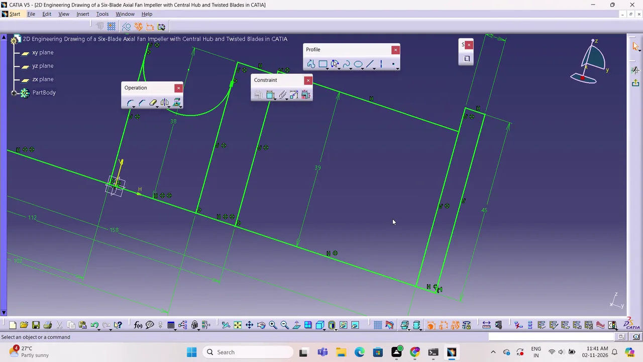
Build a single solid part of a spiral-type pinion shaft as shown in the supplied dimensioned diagrams.
Create and refine a six-blade axial fan impeller in CATIA V5 by constructing constrained sketches, troubleshooting profile topology, generating shaft, pad, pattern, and multi-section features, and saving the resulting CATPart model.
Task set
task.pdfThe task: statement, rubrics and every drawing sheet2 MB↗task_desc.jsonThe task as data: statement, input files and deliverables3 KB↗rubrics.jsonThe rubrics as data2 KB↗references.zipThe drawing sheets and close-ups the task works from2 MB↓gold.zipThe finished files: native and neutral exports429 KB↓