Model a flanged ball valve body with square actuator pad
- Software
- Siemens NX
- Platform
- Windows
- Length
- 1 h 30 min
- Resolution
- 1920 × 1080
- Output
- PRT, STP
Windows
Task
Model a flanged ball valve body with a square actuator mounting pad as a single solid part in millimetres, then produce a dimensioned drawing of it. Work from the supplied dimensioned diagrams: diagram_01.png and its detail views diagram_01_detail01.png to diagram_01_detail04.png.
Body and flanges:
- The body is a horizontal flow passage with an end flange at each end.
- The overall face-to-face length is 328 mm.
- Between the flanges, the body is a double-tapered, barrel-like shell. Two conical halves meet at the mid-plane and blend into the flanges with small fillets.
- Each end flange is a circular disc of Ø200 with a Ø196 diameter as dimensioned on the front view.
- Each flange has six through bolt holes equally spaced on a bolt circle.
- Each flange has a central bore through the flow passage.
Neck and actuator pad:
- A cylindrical neck rises vertically from the top of the body to a square actuator mounting pad.
- The pad is 200 mm square with R20 corner radii.
- The pad has four through holes on a square pattern. On the top view these are located 84 mm from each flange face and 80 + 80 mm apart along the flow axis.
- A central stem bore of Ø48 passes down through the pad and neck.
- The stem bore has a Ø55 counterbore at the pad top face.
Vertical dimensions:
- From the flow axis to the underside of the body: 100 mm.
- From the flow axis to the neck reference: 80 mm.
- From that reference to the top of the pad: 105 mm.
- Total height: 285 mm.
The finished solid should measure approximately 200 × 328 × 285 mm overall.
Part file:
Save the model as FLANGED_VALVE_BODY.prt containing one solid body.
Drawing:
- Create the drawing in FLANGED_VALVE_BODY_dwg1.prt on one sheet in third angle projection.
- Show a top view, a front view, a side or section view and an isometric view. Hidden edges should be shown in the orthographic views.
- Dimension the views, including R20 on the pad, the Ø55 counterbore, the Ø48 stem bore, the Ø200 flanges and the 200 pad width.
- Include a title block with a title, a drawing number and the sheet number (1 OF 1).
- State that dimensions are in millimetres.
ReferenceSheet 1
Loading the drawing
Rubrics16
- R1
The model shall consist of a single solid body with overall extents of approximately 200 × 328 × 285 mm.
- R2
The model shall have a flange-to-flange (face-to-face) length of 328 mm along the flow axis.
- R3
The model shall have a circular flange of Ø200 at each end of the flow passage.
- R4
The model shall have six through bolt holes equally spaced on a bolt circle in each end flange.
- R5
The model shall have a through flow bore along the body axis.
- R6
The model shall have a double-tapered body between the flanges formed by two conical halves meeting at the mid-plane.
- R7
The model shall have a cylindrical neck connecting the body to a square actuator mounting pad 200 mm wide.
- R8
The model shall have R20 corner radii on the square actuator pad.
- R9
The model shall have four through mounting holes in the actuator pad, spaced 160 mm (80 + 80) apart along the flow axis.
- R10
The model shall have a Ø48 stem bore through the pad and neck with a Ø55 counterbore at the pad top face.
- R11
The model shall place the pad top face 285 mm above the body underside, with the flow axis 100 mm above the underside.
- R12
The drawing shall contain top, front and isometric views and a side or section view, in third angle projection.
- R13
The drawing shall dimension R20 on the pad, the Ø55 counterbore and the Ø48 stem bore.
- R14
The drawing shall dimension the Ø200 flanges and the 200 pad width.
- R15
The drawing shall include a title block with a title, a drawing number and sheet 1 OF 1.
- R16
The model shall be saved as FLANGED_VALVE_BODY.prt and the drawing as FLANGED_VALVE_BODY_dwg1.prt.
Gold outputFLANGED_VALVE_BODYPRT, STP
1 of 2Loading
Drag to turn, then scroll to zoom
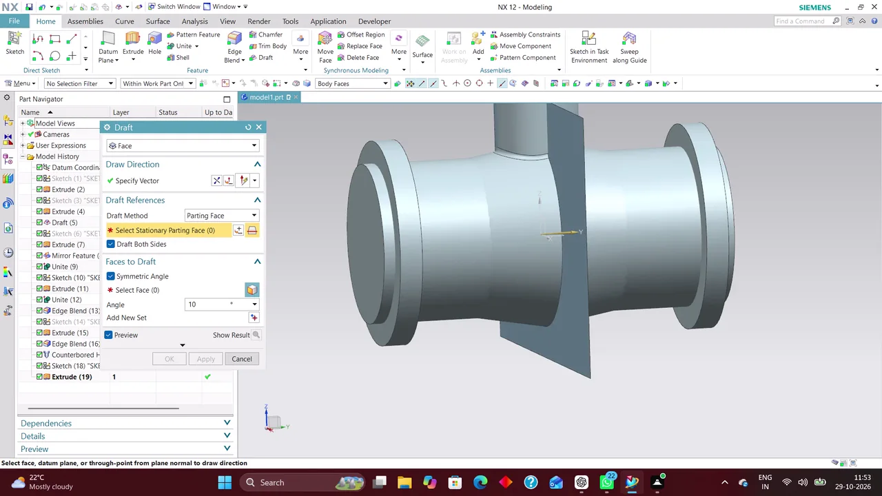
Model a flanged ball valve body with a square actuator mounting pad as a single solid part in millimetres, then produce a dimensioned A3 drawing of it.
Create and refine a Siemens NX flanged valve body from sketches and solid features, then produce and annotate a multi-view technical drawing with section views, dimensions, centerlines, and populated title-block metadata.
Task set
task.pdfThe task: statement, rubrics and every drawing sheet2 MB↗task_desc.jsonThe task as data: statement, input files and deliverables4 KB↗rubrics.jsonThe rubrics as data2 KB↗references.zipThe drawing sheets and close-ups the task works from2 MB↓gold.zipThe finished files: native and neutral exports720 KB↓