Model a sloped-front sheet-metal control box housing
- Software
- SOLIDWORKS
- Platform
- Windows
- Length
- 40 min
- Resolution
- 2560 × 1600
- Output
- SLDPRT, STEP, X_T
Windows
Task
Model a control box housing as a single multibody sheet-metal part in millimetres. Use the supplied dimensioned diagrams diagram_01.png and diagram_01_detail01.png through diagram_01_detail04.png as the reference for size and feature layout.
Build the housing from a solid block, then convert it to sheet metal.
- Block: Sketch a 280 × 350 mm footprint and extrude it 120 mm high.
- Sloped front: Chamfer one top edge 60 × 100 mm. The side profile then shows a 102.77 mm sloped segment and a 247.23 mm flat segment.
- Split lines: Add split lines that define the top opening and the two front window regions.
- Fillet and shell: Round the bend edges with R10 fillets. Shell the body to 1 mm wall thickness.
- Corner reliefs: Cut thin 8 mm corner reliefs and mirror them left-right and front-back.
- Mounting holes: Add six Ø6 mounting holes, three on each side flange, using the Hole Wizard.
- Bodies: Split off the two side panels so the part ends up with three bodies: the main housing and two side panels.
- Sheet metal: Convert each body to sheet metal with flatten/process bends so that each has its own sheet-metal and flat-pattern definition.
Add the following features on the formed housing:
- Rectangular flanges: Two 30 × 20 mm rectangular flange forms, placed as one instance plus its mirror.
- Round flange: One Ø12.7 mm round flange form. It is centred between the rectangular flanges and dimensioned R8.85 on the top view.
- Fan vent: A circular fan vent made with the Vent feature from a dimensioned vent sketch.
- D cutouts: A D-shaped cutout inserted as a library feature and linearly patterned to 2 instances at 90 mm spacing.
- D-sub cutout: A D-sub connector cutout inserted as a library feature.
- Perforations: A hexagonal perforation pattern on both side panels, 227 instances each, with 10 mm hexagons at 15 mm spacing.
Assign Plain Carbon Steel as the material. Set these custom properties:
- Description: "Control box housing - 1 mm sheet-metal enclosure with sloped front, perforated side panels, fan vent, D-sub and D cutouts"
- PartNo: "Control-Box-Housing"
- Material: "Plain Carbon Steel"
Give every sketch and feature a descriptive name, for example "Housing Block 280x350x120", "Housing Shell 1mm" and "Side Panel Perforation Pattern". Fully define all sketches. Keep a single Default configuration. Overall envelope: 280 × 350 × 120 mm.
ReferenceSheet 1
Loading the drawing
Rubrics17
- R1
The model shall have an overall bounding box of 280 mm × 350 mm × 120 mm.
- R2
The model shall be built from a 280 × 350 mm footprint sketch extruded 120 mm.
- R3
The model shall include a 60 × 100 mm chamfer forming the sloped front.
- R4
The model shall include R10 edge fillets and a 1 mm shell.
- R5
The model shall contain three solid bodies: the main housing and two side panels.
- R6
The model shall define three sheet-metal bodies, each with its own flat pattern feature.
- R7
The model shall include six Ø6 mounting holes created with the Hole Wizard.
- R8
The model shall include a 30 × 20 mm rectangular flange form tool instance and its mirror.
- R9
The model shall include a Ø12.7 mm round flange form tool instance.
- R10
The model shall include a fan vent created with the Vent feature from a dimensioned sketch.
- R11
The model shall include a D cutout library feature linearly patterned to 2 instances at 90 mm spacing.
- R12
The model shall include a D-sub connector cutout library feature.
- R13
The model shall include a hexagonal perforation pattern of 227 instances at 15 mm spacing on each side panel.
- R14
The model shall be assigned the material Plain Carbon Steel.
- R15
The model shall carry custom properties Description, PartNo "Control-Box-Housing" and Material "Plain Carbon Steel".
- R16
The model shall use descriptive feature names such as "Housing Block 280x350x120" and "Housing Shell 1mm".
- R17
The model shall contain a single configuration named Default.
Gold outputControl-Box-HousingSLDPRT, STEP, X_T
Loading
Drag to turn, then scroll to zoom
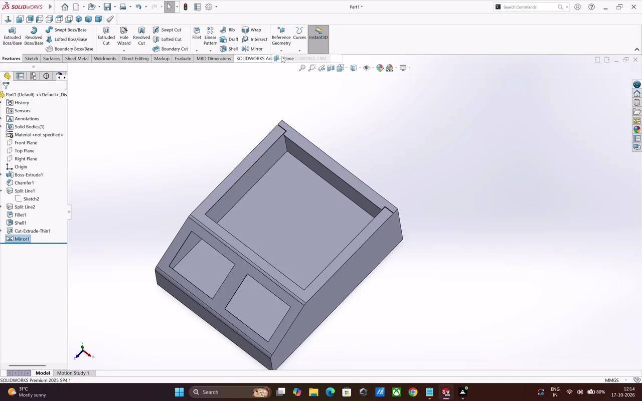
Model a control box housing as a single multibody sheet-metal part in millimetres.
Model a detailed sheet-metal control-box enclosure in SOLIDWORKS, adding extrusions, chamfers, fillets, shelling, vents, holes, patterns, forming tools, and mirrored features. Flatten and export the part to DXF, then save the completed model as “Control-Box-Housing.”
Task set
task.pdfThe task: statement, rubrics and every drawing sheet4 MB↗task_desc.jsonThe task as data: statement, input files and deliverables4 KB↗rubrics.jsonThe rubrics as data2 KB↗references.zipThe drawing sheets and close-ups the task works from3 MB↓gold.zipThe finished files: native and neutral exports6 MB↓