Model reinforced isolated footings on an irregular column grid
- Software
- Autodesk Revit
- Platform
- Windows
- Length
- 14 h 37 min
- Resolution
- 1920 × 1080
- Output
- RVT
Windows
Task
Model a reinforced concrete isolated footing foundation on an irregular column grid, using the supplied dimensioned diagrams diagram_01.png, diagram_01_detail01.png, diagram_01_detail02.png, diagram_01_detail03.png and diagram_01_detail04.png. Work in imperial units (feet and inches).
Grid: create eight lettered grid lines A to H and seven numbered grid lines 1 to 7. The lettered grid spacings, left to right, are A–B 7'-9", B–C 1'-9", C–D 2'-3 1/2", D–E 3'-4 1/2", E–F 5'-8 1/2", F–G 5'-10 1/2" and G–H 2'-6" (29'-3" overall). The numbered grid spacings, bottom to top, are 1–2 15'-1 1/2", 2–3 17'-1 1/2", 3–4 7'-9", 4–5 7'-1 1/2", 5–6 9'-1 1/2" and 6–7 2'-6" (58'-9" overall).
Footings: place rectangular isolated concrete footings at the column locations shown in the diagrams.
- Corner and edge footings are offset so the grid intersection lies at or near a footing edge. Examples are A/7, A/5, H/6, A/1 and H/1.
- Interior footings are roughly centred on their grid intersection. Examples are B/5, D–E/4, D/3, G/3 and G/5.
- One elongated footing along grid A spans from grid 4 to grid 3.
- Further footings are shown at B–C/7, F/7, A/2, C–D/2, G–H/2 and E/1.
Reinforcement: reinforce every footing with a bottom rebar mat running in both directions across its full plan extent. Provide column dowel or stirrup reinforcement at each column position within the footing.
Dimensions and views: dimension both grid directions in the foundation plan with the string dimensions listed above. Place North, South, East and West elevation markers around the plan.
ReferenceSheet 1
Loading the drawing
Rubrics14
- R1
The model shall contain eight lettered grid lines A through H.
- R2
The model shall contain seven numbered grid lines 1 through 7.
- R3
The model shall space the lettered grids A–B 7'-9", B–C 1'-9", C–D 2'-3 1/2" and D–E 3'-4 1/2".
- R4
The model shall space the lettered grids E–F 5'-8 1/2", F–G 5'-10 1/2" and G–H 2'-6".
- R5
The model shall space the numbered grids 1–2 15'-1 1/2", 2–3 17'-1 1/2" and 3–4 7'-9".
- R6
The model shall space the numbered grids 4–5 7'-1 1/2", 5–6 9'-1 1/2" and 6–7 2'-6".
- R7
The model shall contain at least 15 rectangular isolated concrete footings placed at grid intersection locations.
- R8
The model shall include one elongated footing along grid A spanning from grid 4 to grid 3.
- R9
The model shall include footings near intersections A/7, F/7, H/6, A/1, E/1 and H/1, as shown in the diagrams.
- R10
The model shall contain rebar elements forming a bottom mat in two orthogonal directions within each footing.
- R11
The model shall contain column dowel or stirrup rebar at the column position within the footings.
- R12
The drawing shall include string dimensions along both grid directions matching the stated grid spacings.
- R13
The drawing shall include four elevation markers named for the North, South, East and West directions arranged around the plan.
- R14
The model shall use imperial feet-and-inch project units.
Gold outputSTR-REBARRVT
1 of 13Loading
Drag to turn, then scroll to zoom
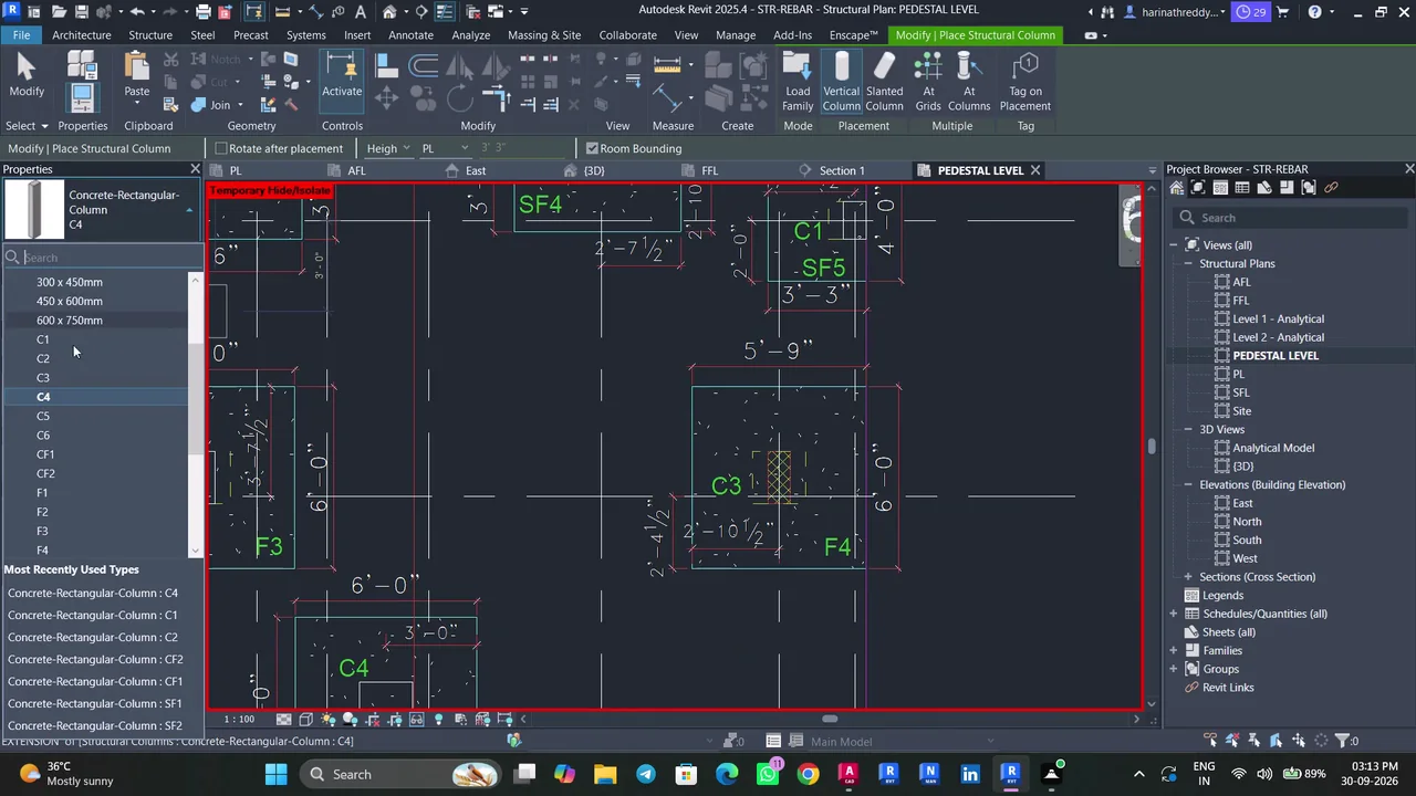
Model a reinforced concrete isolated footing foundation on an irregular column grid, using the supplied dimensioned diagrams diagram_01.png, diagram_01_detail01.png, diagram_01_detail02.png, diagram_01_detail03.png and diagram_01_detail04.p
Developed and reviewed a structural Revit model using AutoCAD floor-detail references, configuring footing, column, beam, floor, stair, and rebar types while placing, adjusting, and inspecting structural elements across plan, section, elevation, and 3D views. Cross-checked dimensions, reinforcement schedules, cover settings, visibility, and detailing against the CAD drawings.
Task set
task.pdfThe task: statement, rubrics and every drawing sheet548 KB↗task_desc.jsonThe task as data: statement, input files and deliverables2 KB↗rubrics.jsonThe rubrics as data2 KB↗references.zipThe drawing sheets and close-ups the task works from1 MB↓gold.zipThe finished files: native and neutral exports11 MB↓