Model an oscillating wobbler steam engine assembly
- Software
- SOLIDWORKS
- Platform
- Windows
- Length
- 4 h 36 min
- Resolution
- 1920 × 1080
- Output
- SLDASM, SLDPRT, STEP, X_T
Windows
Task
Model a miniature oscillating (wobbler) steam engine as an eight-part assembly, following the supplied dimensioned diagrams (diagram_01.png through diagram_09.png and their detail views). Model the parts in inches, matching the fractional-inch sizes on the sheets. The assembly is presented in millimetres. Overall envelope is about 67.64 x 43.66 mm in the top and front views.
Parts, one of each:
1. COLUMN: a revolved display column 66.67 mm (2.625 in) tall on a Ø34.92 mm (1.375 in) base ring. It has a 1.27 x 45° chamfer, upper and lower flats, small holes, a cross hole and a relief cut.
2. BEARING: a flanged sleeve bushing 17.46 mm (11/16 in) long. Flange Ø9.53 mm (3/8 in), shank Ø7.94 mm (5/16 in), through bore Ø4.76 mm (3/16 in), R0.005 in edge fillet.
3. CRANKSHAFT: a half-disc crank web of Ø17.46 mm, 3.97 mm thick, with a crank pin and a Ø4.76 mm (0.1875 in) x 31.75 mm (1.25 in) main shaft.
4. FLYWHEEL: Ø31.75 mm (1.25 in) x 7.94 mm (5/16 in) with a Ø4.76 mm bore. It has mirrored Ø22.23 mm (0.875 in) face recesses, mirrored Ø9.53 mm (0.375 in) hub bosses and a radial set-screw hole.
5. CYLINDER: an octagonal body 28.58 mm (1.125 in) long with a Ø9.53 mm bore, an end collar, recesses and an integral rod.
6. PISTON: a revolved piston head with an integral rod, ending in a 6.35 mm clevis block with a cross pin hole. Overall length along the rod axis is 38.1 mm.
7. WASHER: Ø0.406 in OD x Ø0.141 in ID x 0.045 in thick.
8. NUT: a hex nut 0.312 in (7.92 mm) across flats and 0.114 in thick, with a Ø1/8 in bore and a double-sided 30° corner chamfer.
Part modelling requirements:
- Build each part from fully defined sketches.
- Give sketches and features descriptive names.
- Assign a steel material to every part.
- Fill in the custom properties Description, PartNo and Material.
Assembly requirements:
- Fix the column.
- Locate all other components with concentric, coincident and tangent mates so that there are no mate errors.
- Arrange the parts as shown in the isometric and right side views: bearing in the column, crankshaft through the bearing, flywheel on the shaft, and cylinder pivoting on the column with washer and nut.
- Give the assembly the custom properties Description, PartNo and Material.
ReferenceSheet 1
1 of 9Loading the drawing
Rubrics16
- R1
The model shall be an assembly containing exactly eight resolved, unsuppressed components: column, bearing, crankshaft, flywheel, cylinder, piston, washer and nut.
- R2
The model's column part shall be a revolved body 66.67 mm (2.625 in) tall with a Ø34.92 mm base ring and a 1.27 x 45° chamfer.
- R3
The model's column shall include flats and cross-hole cut features.
- R4
The model's bearing shall be a flanged bushing 17.46 mm long with a Ø9.53 mm flange, a Ø7.94 mm shank and a Ø4.76 mm through bore.
- R5
The model's crankshaft shall have a half-disc web of Ø17.46 mm, a crank pin, and a main shaft of Ø4.76 mm x 31.75 mm.
- R6
The model's flywheel shall be Ø31.75 mm x 7.94 mm with a Ø4.76 mm bore, mirrored Ø22.23 mm face recesses, mirrored Ø9.53 mm hub bosses and a radial set-screw hole.
- R7
The model's cylinder shall have an octagonal body 28.58 mm long with a Ø9.53 mm bore and an integral rod.
- R8
The model's piston shall have a revolved head and rod with a 6.35 mm clevis block containing a cross pin hole, 38.1 mm overall along the rod axis.
- R9
The model's washer shall be Ø0.406 in OD x Ø0.141 in ID x 0.045 in thick.
- R10
The model's nut shall be a hex 0.312 in (7.92 mm) across flats and 0.114 in thick, with a Ø1/8 in bore and a 30° corner chamfer on both sides.
- R11
The model's assembled envelope shall be approximately 67.64 mm by 43.66 mm in the top/front view directions.
- R12
The model shall have the column component fixed and all other components positioned by mates.
- R13
The model shall use concentric, coincident and tangent mates, with no mate errors.
- R14
The model's part features and sketches shall carry descriptive names, e.g. 'Flanged Bushing Body' and 'Main Shaft Ø0.1875'.
- R15
The model's parts shall each have a steel material assigned.
- R16
The model's parts and assembly shall each carry Description, PartNo and Material custom properties.
Gold outputAssem2SLDASM, STEP, X_T
1 of 9Loading
Drag to turn, then scroll to zoom
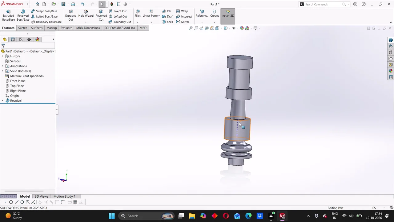
Model a miniature oscillating (wobbler) steam engine as an eight-part assembly, following the supplied dimensioned diagrams (diagram_01.png through diagram_09.png and their detail views).
Create and refine multiple SolidWorks parts, apply features and appearances, save/export them with component names, then assemble the components into a mechanical engine-like assembly with mates and a rotary motion study.
Task set
task.pdfThe task: statement, rubrics and every drawing sheet12 MB↗task_desc.jsonThe task as data: statement, input files and deliverables12 KB↗rubrics.jsonThe rubrics as data3 KB↗references.zipThe drawing sheets and close-ups the task works from12 MB↓gold.zipThe finished files: native and neutral exports3 MB↓