Model a flanged water control ball valve assembly with eight parts
- Software
- CATIA V5
- Platform
- Windows
- Length
- 7 h 25 min
- Resolution
- 1920 × 1080
- Output
- CATPRODUCT, CATPART
Windows
Task
Build a 3D model of a flanged ball-type water control valve as a product assembly. Work in millimetres. Model each component as its own part, then assemble the parts in a top-level product named water_control_valve_assembly. Overall arrangement and views are on diagram_01.png. Part dimensions are on diagram_01_sheet2.png (ball valve), diagram_01_sheet3.png (inlet housing) and diagram_01_sheet4.png (cap screw), with their detail images.
Name the eight parts exactly: INLET_HOUSING, OUTLET_HOUSING, BALL_VALVE_SUB, CAP_SCREW, THERMOSTAT_FLANGE, LOCK_LEVER, HANDLE, HEXAGONAL_BOLT.
INLET_HOUSING:
- Ø152.4 end flange with four Ø19.1 bolt holes.
- Ø50.8 through bore.
- Ø127 mating flange at the opposite end with four Ø12.7 holes.
- Flanges 16.5 thick, with 102.9 between the flange faces.
- 69.9 tapered body section.
- 9.7 thick top mounting pad with a central Ø25.4 hole and two side holes, outlined by R24.15, R12.7 and R50.8 arcs.
BALL_VALVE_SUB:
- Ø52.8 ball with a Ø38.1 through bore, trimmed to flats 34.92 apart and 39.6 tall.
- Ø25.4 stem, 61.56 long.
- 20.9 × 20.9 square tang, 31 long, with 14.43 across the tang.
- 115.7 from the ball centre to the stem top.
CAP_SCREW:
- 41.4 overall length.
- Ø9.7 shank, with 29.5 from the collar underside to the shank end.
- Ø17.3 collar, 2.3 thick.
- Ø11.7 head with a hexagonal socket 6.06 across.
- 1 × 45° chamfer on the head and 1.16 × 45° chamfer on the shank end.
HEXAGONAL_BOLT:
- 40.89 overall length.
- Ø12.70 shank, 28.19 long under the flange, ending in a 1.16 × 45° chamfer.
- Ø24.64 flange, 3.30 thick.
- Hexagon head on an R11.05 corner circle.
HANDLE:
- Flat lever 246 long overall and 20 wide, with an R10 tip.
- R22 hub, 22 tall, with a 21 square socket for the tang.
- Arm cranked through R51 bends at 135° and 137°.
- Ø4 stop pin, 10 long.
OUTLET_HOUSING, THERMOSTAT_FLANGE and LOCK_LEVER:
- Proportion these parts to the assembly views and to their mating features.
- OUTLET_HOUSING has a Ø127 mating flange matching the inlet's four Ø12.7 holes, a Ø50.8 bore and a Ø152.4 end flange.
- THERMOSTAT_FLANGE sits on the top pad, passes the Ø25.4 stem and takes four Ø9.7 cap screws.
- LOCK_LEVER is a plate on the stem.
Assembly:
- Inlet and outlet housings coaxial along the flow axis.
- Ball seated in the body with the stem vertical.
- Thermostat flange on the top pad, held by four cap screws.
- Lock lever on the stem, with two hexagonal bolts at the housing joint.
- Handle on the square tang, extending sideways.
The product contains 12 instances of 8 parts: 4 × CAP_SCREW, 2 × HEXAGONAL_BOLT and one each of the other six.
ReferenceSheet 1, page 1
1 of 6Loading the drawing
Rubrics18
- R1
The model shall include an INLET_HOUSING part with a Ø152.4 end flange carrying four Ø19.1 holes.
- R2
The INLET_HOUSING shall have a Ø50.8 through bore along the flow axis.
- R3
The INLET_HOUSING shall have a Ø127 mating flange with four Ø12.7 holes at the opposite end from the Ø152.4 flange.
- R4
The INLET_HOUSING shall have flanges 16.5 thick and a 102.9 dimension between its flange faces.
- R5
The INLET_HOUSING shall carry a 9.7 thick top mounting pad with a central Ø25.4 hole.
- R6
The BALL_VALVE_SUB part shall have a Ø52.8 spherical ball with a Ø38.1 through bore.
- R7
The BALL_VALVE_SUB ball shall be trimmed to parallel flats 34.92 apart.
- R8
The BALL_VALVE_SUB shall have a Ø25.4 stem 61.56 long ending in a 20.9 × 20.9 square tang 31 long.
- R9
The BALL_VALVE_SUB shall measure 115.7 from the ball centre to the top of the stem.
- R10
The CAP_SCREW part shall be 41.4 long overall with a Ø9.7 shank and a Ø17.3 collar 2.3 thick.
- R11
The CAP_SCREW shall have a Ø11.7 head with a hexagonal socket 6.06 across.
- R12
The CAP_SCREW shall have a 1 × 45° chamfer on the head and a 1.16 × 45° chamfer on the shank end.
- R13
The HEXAGONAL_BOLT part shall be 40.89 long overall with a Ø12.70 shank and a Ø24.64 flange.
- R14
The model shall be built in millimetre units.
- R15
The model shall be organised as a product named water_control_valve_assembly referencing separate parts INLET_HOUSING, OUTLET_HOUSING, BALL_VALVE_SUB, CAP_SCREW, THERMOSTAT_FLANGE, LOCK_LEVER, HANDLE and HEXAGONAL_BOLT.
- R16
The product shall contain 12 component instances: 4 CAP_SCREW, 2 HEXAGONAL_BOLT and one each of the other six parts.
- R17
The assembly shall position the inlet and outlet housings coaxially along the flow axis.
- R18
The assembly shall position the ball valve stem vertically, with the handle fitted on its square tang.
Gold outputwater_control_valve_assemblyCATPRODUCT
1 of 9Loading
Drag to turn, then scroll to zoom
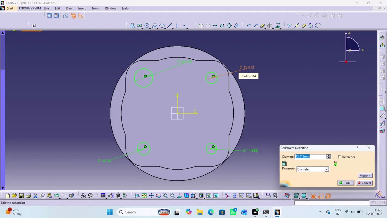
Build a 3D model of a flanged ball-type water control valve as a product assembly.
Created and refined a CATIA V5 water-control-valve assembly from multiple modeled components, applying features, constraints, materials, and assembly relationships. Produced detailed multi-sheet engineering drawings with projections, dimensions, title blocks, notes, bills of materials, and PDF export preparations.
Task set
task.pdfThe task: statement, rubrics and every drawing sheet4 MB↗task_desc.jsonThe task as data: statement, input files and deliverables8 KB↗rubrics.jsonThe rubrics as data3 KB↗references.zipThe drawing sheets and close-ups the task works from5 MB↓gold.zipThe finished files: native and neutral exports1 MB↓