Draft hospital essential supply single-line distribution schematic
- Software
- AutoCAD
- Platform
- Windows
- Length
- 2 h 01 min
- Resolution
- 1920 × 1080
- Output
- DWG, DXF
Windows
Task
Draft a single-line distribution schematic for a hospital essential electrical supply on one sheet. Use inch units, not to scale. No dimensions or hatching are needed.
At the top, draw a horizontal 11 kV overhead feeder line that ends in a large arrowhead at the left, labelled "UTILITY 11KV". Draw two vertical transformer branches off this line. Each branch has:
- a lightning arrester labelled "LA";
- a drop-out fuse drawn as two arcs, labelled "3P 100A";
- a transformer drawn as two circles, each containing a triangle;
- an outgoing Q0 breaker drawn with circle contacts and a diagonal blade.
The left branch is labelled "TR-1 1250KVA 3 433V" and "Q0 160A". It feeds board "EMDB-01", marked "EXISTING", with "ACB INCOMER 3P 630A". Its horizontal busbar has four feeders:
- F1 160A, OT DB 4CX25MM2
- F2 160A, ICU DB 4CX70MM2
- F3 200A, LIFE SAFETY 4CX50MM2
- F4 63A, UPS INPUT 4CX95MM2
The right branch is labelled "TR-2 1250KVA 3 433V" and "Q0500A". It feeds "LDB-02", marked "NEW INSTALLATION", with "ACB INCOMER 3P 400A". Its busbar has seven feeders:
- F1 32A, OT DB 4CX25MM2
- F2 100A, ICU DB 4CX70MM2
- F3 250A, LIFE SAFETY 4CX50MM2
- F4 125A, UPS INPUT 4CX95MM2
- F5 100A, HVAC DB 4CX25MM2
- F6 63A, LIFT DB 4CX70MM2
- F7 63A, SPARE 4CX25MM2
Each feeder has a breaker with circle contacts and ends in a triangular arrow. Each feeder carries its rating and its cable label as listed above.
Add a METERING element with a "V5" box and an ammeter "A". Add a rectangular box labelled "APFC/CAP BANK" and "12 STEP 100KVA". Connect it to the LDB-02 busbar and place capacitor symbols inside it. Draw a PE bar line under each board. Insert a title block border.
CAD standards (all objects ByLayer colour, linetype and lineweight; nothing on layer 0):
- E-ONEL (ACI 7, Continuous, 0.35 mm): all schematic lines, circles and arcs.
- E-ONEL-SYMB (ACI 4, Continuous, 0.25 mm): symbol blocks. Use block LIGHTNING-ARRESTER for both arresters (2 references) and block CAPACITOR-STEP for the capacitor symbols (2 references).
- E-ANNO-TEXT (ACI 3, Continuous, 0.25 mm): all labels, as MTEXT.
- E-ANNO-TTLB (ACI 7, Continuous, 0.25 mm): title block references NO_NUM_acade_title and WD_M, one each.
ReferenceSheet 1
Loading the drawing
Rubrics18
- R1
The drawing shall show a horizontal 11 kV feeder line with a left-end arrowhead labelled "UTILITY 11KV".
- R2
The drawing shall show two transformer branches, each with a drop-out fuse drawn as arcs, a transformer of two circles with triangles, and a Q0 breaker.
- R3
The drawing shall show a lightning arrester labelled "LA" on each transformer branch.
- R4
The drawing shall show an EMDB-01 busbar with exactly four outgoing feeders, each with a breaker and a terminating arrow.
- R5
The drawing shall show an LDB-02 busbar with exactly seven outgoing feeders, each with a breaker and a terminating arrow.
- R6
The drawing shall include an APFC/CAP BANK box connected to the LDB-02 busbar, and a METERING element with a V5 box and an "A" meter.
- R7
The drawing shall label the transformers "TR-1" and "TR-2" with 433V, label the breakers "Q0 160A" and "Q0500A", and label the incomers "ACB INCOMER 3P 630A" and "ACB INCOMER 3P 400A".
- R8
The drawing shall label the feeders with their ratings: EMDB-01 F1 160A, F2 160A, F3 200A, F4 63A; LDB-02 F1 32A, F2 100A, F3 250A, F4 125A, F5 100A, F6 63A, F7 63A.
- R9
The drawing shall label the feeder cables with load names and sizes, including OT DB 4CX25MM2, ICU DB 4CX70MM2, LIFE SAFETY 4CX50MM2, UPS INPUT 4CX95MM2, HVAC DB 4CX25MM2, LIFT DB 4CX70MM2 and SPARE 4CX25MM2.
- R10
The drawing shall include the board tags "EMDB-01" and "LDB-02", the notes "EXISTING" and "NEW INSTALLATION", and the text "12 STEP 100KVA".
- R11
The drawing shall contain layers E-ONEL (ACI 7, Continuous, 0.35 mm), E-ONEL-SYMB (ACI 4, Continuous, 0.25 mm), E-ANNO-TEXT (ACI 3, Continuous, 0.25 mm) and E-ANNO-TTLB (ACI 7, Continuous, 0.25 mm).
- R12
The drawing shall place all schematic lines, circles and arcs on layer E-ONEL.
- R13
The drawing shall place all text (MTEXT) on layer E-ANNO-TEXT.
- R14
The drawing shall define block LIGHTNING-ARRESTER and insert it 2 times on layer E-ONEL-SYMB, once for each arrester.
- R15
The drawing shall define block CAPACITOR-STEP and insert it 2 times on layer E-ONEL-SYMB within the APFC bank.
- R16
The drawing shall insert the title block blocks NO_NUM_acade_title and WD_M once each on layer E-ANNO-TTLB.
- R17
The drawing shall have every object's colour, linetype and lineweight set to ByLayer.
- R18
The drawing shall have no drawing geometry on layer 0.
Gold outputELECTRICAL_SUPPLYDWG, DXF
Loading
Drag to move, then scroll to zoom
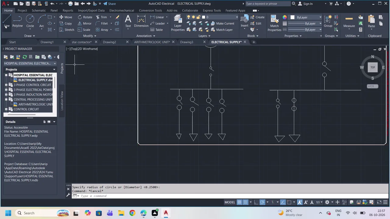
Draft a single-line distribution schematic for a hospital essential electrical supply on one sheet.
Create and annotate an AutoCAD Electrical project named “HOSPITAL ESSENTIAL ELECTRICAL SUPPLY” with an “ELECTRICAL SUPPLY” drawing, adding schematic geometry, symbols, component ratings, feeder labels, cable specifications, and installation notes.
Task set
task.pdfThe task: statement, rubrics and every drawing sheet720 KB↗task_desc.jsonThe task as data: statement, input files and deliverables3 KB↗rubrics.jsonThe rubrics as data3 KB↗references.zipThe drawing sheets and close-ups the task works from748 KB↓gold.zipThe finished files: native and neutral exports80 KB↓