Draft the front elevation of a multi-storey commercial tower with podium
- Software
- AutoCAD
- Platform
- Windows
- Length
- 2 h 39 min
- Resolution
- 1366 × 768
- Output
- DWG, DXF
Windows
Task
Draft, in 2D at full size with drawing units set to inches, a single front elevation of a multi-storey commercial building, as shown on the supplied dimensioned diagram diagram_01.png. The overall extent is 1710.08 wide by 1813.9 high.
Horizontal divisions along the base, left to right, are 448.23, 242.87, 700.8 and 318.18. Vertical divisions, bottom to top, are 451.9 (podium), then 288, 294, 258 and 264 (tower shaft), then 258 (rooftop crown).
Composition, bottom to top:
- A low podium on a continuous ground/plinth line.
- At left are two stepped, horizontally banded blocks with sloping parapets.
- Next is a fully glazed, gridded curtain-wall volume containing a double entrance door.
- The centre has a splayed wall with a second, larger double door.
- At right is a glazed block with curtain-wall grids.
- A tower shaft above the podium:
- A canted (inclined) left frame enclosing six cantilevered horizontal balcony/slab bands, each with a small glazed corner panel at its left end.
- Six short floor projections down the left edge.
- A vertical brick-clad pier and a brick-clad top band.
- A tall vertical feature column at the right, with a square-box infill pattern.
- A recessed rooftop crown: two gridded parapet tiers, then a smaller gridded plant enclosure, topped by a sloped mechanical penthouse.
- A rectangular border frame around the whole drawing.
No dimensions or text are required in the drawing.
CAD standards:
- Create the following layers:
- A-ELEV (ACI 7, Continuous, 0.35 mm): all building outline, massing, banding, roof and border linework, using lines and polylines.
- A-GLAZ (ACI 4, Continuous, 0.18 mm): all curtain-wall and window mullion/transom grid lines.
- A-DOOR (ACI 3, Continuous, 0.25 mm): the entrance door leaves and frames.
- A-ELEV-PATT (ACI 8, Continuous, 0.13 mm): material hatches.
- Use native hatches only:
- BOX pattern for the right feature column (3 hatch objects).
- AR-BRSTD for the brick pier and brick top band (2 hatch objects).
- All objects take colour, linetype and lineweight ByLayer.
- Nothing is drawn on layer 0.
ReferenceSheet 1
Loading the drawing
Rubrics14
- R1
The drawing shall contain a single front elevation showing a podium, a tower shaft and a recessed rooftop crown/penthouse.
- R2
The drawing shall show six cantilevered horizontal balcony/slab bands within a canted (inclined) frame on the tower.
- R3
The drawing shall show a vertical feature column at the right side of the tower and a brick-clad pier with a brick top band.
- R4
The drawing shall show podium glazing with curtain-wall grids and two entrance double doors.
- R5
The drawing shall show a stepped rooftop with gridded parapet tiers and a sloped mechanical penthouse at the top.
- R6
The drawing shall include a rectangular border frame enclosing the elevation and a continuous ground/plinth line.
- R7
The drawing shall use inches as its units, at full size, with an overall extent of approximately 1710.08 wide by 1813.9 high.
- R8
The drawing shall contain layer A-ELEV with ACI 7, Continuous linetype and 0.35 mm lineweight, holding the building outline linework (lines and polylines).
- R9
The drawing shall contain layer A-GLAZ with ACI 4, Continuous linetype and 0.18 mm lineweight, holding the glazing grid lines.
- R10
The drawing shall contain layer A-DOOR with ACI 3, Continuous linetype and 0.25 mm lineweight, holding the door linework.
- R11
The drawing shall contain layer A-ELEV-PATT with ACI 8, Continuous linetype and 0.13 mm lineweight, holding all hatches.
- R12
The drawing shall fill the feature column with native BOX pattern hatches (3 hatch objects) on A-ELEV-PATT, not exploded lines.
- R13
The drawing shall fill the brick areas with native AR-BRSTD pattern hatches (2 hatch objects) on A-ELEV-PATT, not exploded lines.
- R14
The drawing shall have no geometry on layer 0.
Gold outputmulti_storey_elevationDWG, DXF
Loading
Drag to move, then scroll to zoom
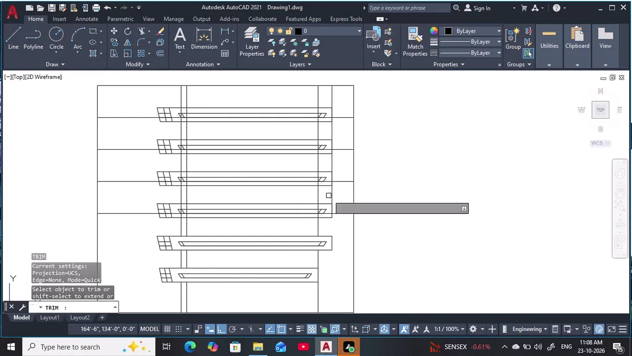
Draft, in 2D at full size with drawing units set to inches, a single front elevation of a multi-storey commercial building, as shown on the supplied dimensioned diagram diagram_01.png.
Developed and edited a multi-storey building elevation in AutoCAD using line, offset, trim, extend, move, hatch, and dimension tools, then saved it as “multi storey elevation.dwg.” Configured a DWG-to-PDF plot, exported the drawing, and reviewed the resulting PDF in Microsoft Edge.
Task set
task.pdfThe task: statement, rubrics and every drawing sheet438 KB↗task_desc.jsonThe task as data: statement, input files and deliverables3 KB↗rubrics.jsonThe rubrics as data2 KB↗references.zipThe drawing sheets and close-ups the task works from270 KB↓gold.zipThe finished files: native and neutral exports76 KB↓