Model a steel access staircase with two landings and handrails
- Software
- CATIA V5
- Platform
- Windows
- Length
- 4 h 03 min
- Resolution
- 1920 × 1080
- Output
- CATPART, CATPRODUCT, CATDRAWING
Windows
Task
Build a complete 3D model and a two-sheet drawing of a steel access staircase with two landings, handrails and grating steps. Work in millimetres and follow the supplied dimensioned diagrams diagram_01.png, diagram_01_detail01.png, diagram_01_detail02.png, diagram_01_sheet2.png, diagram_01_detail03.png and diagram_01_detail04.png.
Structure layout:
- Lower landing: 1600 x 2250 mm in plan. Its deck sits 3360 mm above ground (1680 + 1680), with an intermediate bracing level. It stands on four columns.
- Upper landing: 700 x 1100 mm in plan. Its deck sits 7000 mm above ground on a four-column tower braced at 2350, 2350 and 2300 mm intervals. The tower columns are 700 mm apart in the front view.
- Front-view spacing: 1600 mm between the lower-landing columns and 4000 mm from the lower landing to the tower, for an overall length of 7100 mm.
- Lower flight: 900 mm clear width (1000 mm overall). It runs from the ground to the lower landing with a 5100 mm sloped length and a 3800 mm horizontal projection.
- Upper flight: 1100 mm wide, with a 5250 mm sloped length. It rises from the lower landing to the upper landing.
Detail parts:
- Every column ends in an MS stub base: a column stub welded to a base plate, with bolt holes (Detail A).
- Each step is a grating tread on L-angle supports. Steps are spaced 310 mm along the stringer and 200 mm apart vertically, with a 38 mm grating depth.
- Handrails with posts, mid-rails and toe plates run along both flights and around the landings. The landing guardrails are 1200 mm high.
Model each member type as its own part. Use names such as GRETING, STEP/STEPS, L_ANGLE, MS_STUB, TOE, OMEGA and SQ for the grating, steps, angles, base stubs, toe plates, handrail/omega sections and square columns. Assemble all parts in one product.
Produce an A3 drawing with two sheets:
- Sheet 1: front, right and top views with the overall and level dimensions listed above. Add Detail A (MS stub), an isometric view of a single step (L angle, L angle for support) and an isometric of the step details with the 310, 200 and 38 mm dimensions. Label all views.
- Sheet 2: an isometric view of the whole staircase.
Use the title "STEEL ACCESS STAIRCASE WITH TWO LANDINGS, HANDRAILS AND GRATING STEPS".
ReferenceSheet 1, page 1
1 of 2Loading the drawing
Rubrics15
- R1
The model shall include a lower landing measuring 1600 mm by 2250 mm in plan with its deck at 3360 mm above ground.
- R2
The model shall include an upper landing measuring 700 mm by 1100 mm in plan with its deck at 7000 mm above ground.
- R3
The model shall place the lower-landing columns 1600 mm apart and the tower 4000 mm from the lower landing, giving an overall length of 7100 mm in the front view.
- R4
The model shall include a lower stair flight of 900 mm clear width with a 3800 mm horizontal run from ground to the lower landing.
- R5
The model shall include an upper stair flight 1100 mm wide connecting the lower landing to the upper landing.
- R6
The model shall include grating steps supported on L-angles, spaced 310 mm along the slope and 200 mm vertically.
- R7
The model shall include handrails with posts and toe plates along both flights and around the landings, with landing guardrails 1200 mm high.
- R8
The model shall include an MS stub base with a base plate at the foot of each column.
- R9
The model shall include intermediate horizontal bracing on the tower at 2350 mm intervals and a mid-height bracing level on the lower-landing frame.
- R10
The drawing shall contain a sheet with labelled front, right and top views of the staircase.
- R11
The drawing front view shall show the dimensions 7100, 1600, 4000, 3800, 3360, 7000, 5100 and 5250.
- R12
The drawing shall include Detail A of the MS stub, an isometric step view and an isometric step-details view dimensioned 310, 200 and 38.
- R13
The drawing shall contain a second sheet with an isometric view of the complete staircase.
- R14
The drawing shall carry the title STEEL ACCESS STAIRCASE WITH TWO LANDINGS, HANDRAILS AND GRATING STEPS.
- R15
The model shall be organised as a product assembling separate parts for grating, steps, L-angles, MS stubs, toe plates and handrail sections.
Gold outputProduct1CATPRODUCT
1 of 36Loading
Drag to turn, then scroll to zoom
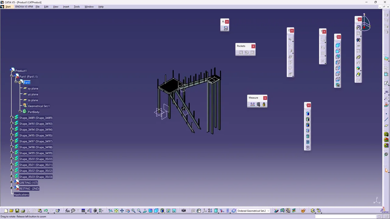
Build a complete 3D model and a two-sheet drawing of a steel access staircase with two landings, handrails and grating steps.
Developed a CATIA industrial stair-and-platform assembly by creating and constraining structural parts, applying pads, patterns, mirrors, translations, and component placements, then renaming and saving assembly components. Produced and refined a CATIA drafting sheet with orthographic, isometric, detail views, dimensions, annotations, and PDF print/export settings.
Task set
task.pdfThe task: statement, rubrics and every drawing sheet1 MB↗task_desc.jsonThe task as data: statement, input files and deliverables17 KB↗rubrics.jsonThe rubrics as data3 KB↗references.zipThe drawing sheets and close-ups the task works from2 MB↓gold.zipThe finished files: native and neutral exports11 MB↓