Model a spur pinion gear shaft with square drive end and detail it on an A3 drawing
- Software
- PTC Creo
- Platform
- Windows
- Length
- 1 h 42 min
- Resolution
- 2880 × 1800
- Output
- DRW, PRT
Windows
Task
Create a solid part model and an associated A3 detail drawing of a spur pinion gear shaft with a square drive end and a center hole. Work in millimetres. Name the part file creo-ex-13.prt and the drawing creo-ex-13.drw.
The shaft is a single turned part, 92 long overall, built on one axis. From the left end:
- Journal: Ø15, 13 long.
- Hub: Ø23, 14 long.
- Spur gear: 40 outside diameter, 31 root diameter, 15 face width. C1 chamfers on the tooth edges.
- Second hub: Ø23. The span from the start of the first hub to the end of this hub is 47.
- Right shaft: Ø15 to the right end. C1.5 chamfer at the end face.
Add an R3 fillet where each hub meets the gear root. Cut a square drive on the last 16 of the right end, 12 across the flats, with a 2 dimension at the start of the flats. Add a 60° center hole to KS B 0410, type A, size 2, in the right end face.
Model the gear teeth evenly spaced around the shaft axis on a Ø36 pitch circle. Size the tooth form with these values:
- A tooth tip width of 1.2.
- R10 flank arcs.
- A separate dimension of 4 at the tooth.
Produce a drawing of the part on an A3 sheet with these views:
- A front view with the axial dimensions 13, 14, 15, 47, 16 and 92, the diameters 15, 23, 40, 23 and 15, and the 2 dimension at the square drive.
- A full longitudinal section view, hatched, showing the 31 root diameter, R3 and C1.5.
- An end view showing the tooth form (R10, 4 and 1.2) and the 12 square across flats.
- An isometric shaded view.
Annotate C1 on the gear and add the center hole note "KS B 0410 60° A 2,".
ReferenceSheet 1
Loading the drawing
Rubrics15
- R1
The model shall be a single solid part 92 mm long overall along one axis.
- R2
The model shall have Ø15 shaft sections at both ends, with a left journal length of 13 mm.
- R3
The model shall have Ø23 hub sections on both sides of the gear, with the first hub 14 mm long and a 47 mm span from the start of the first hub to the end of the second hub.
- R4
The model shall have a spur gear 15 mm wide with a 40 mm outside diameter and a 31 mm root diameter, with teeth evenly spaced around the shaft axis.
- R5
The model shall have C1 chamfers on the gear tooth edges.
- R6
The model shall have R3 fillets where the hubs meet the gear.
- R7
The model shall have a square drive 12 mm across flats extending 16 mm from the right end.
- R8
The model shall have a C1.5 chamfer on the right end and a center hole in the right end face.
- R9
The drawing shall contain a front view, a hatched longitudinal section view, an end view showing the teeth and an isometric view.
- R10
The drawing shall dimension the lengths 13, 14, 15, 47, 16 and 92.
- R11
The drawing shall dimension the diameters 15, 23 and 40 in the front view and 31 in the section view.
- R12
The drawing shall annotate R3, C1, C1.5, R10, 4, 1.2, 2 and 12.
- R13
The drawing shall carry the center hole note "KS B 0410 60° A 2,".
- R14
The drawing shall be on an A3 sheet.
- R15
The drawing shall be file creo-ex-13.drw, referencing the part file creo-ex-13.prt.
Gold outputcreo-ex-13PRT
1 of 2Loading
Drag to turn, then scroll to zoom
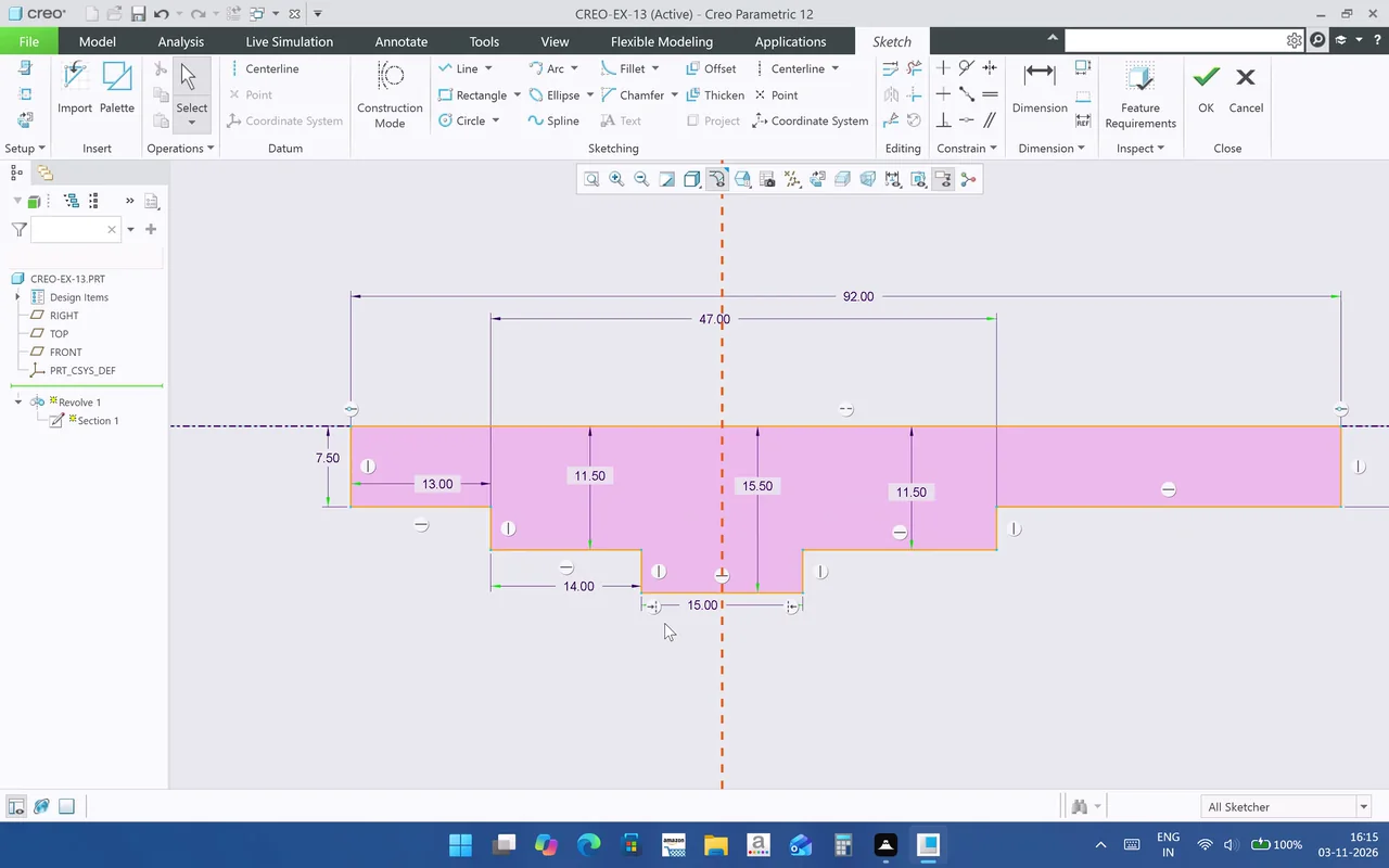
Create a solid part model and an associated A3 detail drawing of a spur pinion gear shaft with a square drive end and a center hole.
Created and refined a Creo Parametric shaft-and-gear part with revolved, extruded, chamfered, patterned, rounded, mirrored, and hole features. Saved the part, produced an annotated engineering drawing with multiple views and sections, and exported the drawing as a PDF.
Task set
task.pdfThe task: statement, rubrics and every drawing sheet404 KB↗task_desc.jsonThe task as data: statement, input files and deliverables3 KB↗rubrics.jsonThe rubrics as data2 KB↗references.zipThe drawing sheets and close-ups the task works from539 KB↓gold.zipThe finished files: native and neutral exports434 KB↓