Model the split cylindrical housing bracket as a 3D solid
- Software
- AutoCAD
- Platform
- Windows
- Length
- 37 min
- Resolution
- 1920 × 1080
- Output
- DWG, DXF
Windows
Task
Build a 3D solid model of a split cylindrical housing bracket. Work in millimetres at full size (1:1). The geometry is defined by the supplied dimensioned diagrams: diagram_01.png (front, top, right side and isometric views, third-angle projection) and its enlarged details diagram_01_detail01.png to diagram_01_detail04.png. Model only the part itself. Do not add 2D views, dimensions or text.
Geometry:
- Head. Two parallel cylindrical bosses, each R18 (36 dia) on the outside. Their axes are horizontal and run front-to-back. Each boss has a 2X Ø18 through-hole on its axis.
- Boss spacing. The overall width across the bosses is 96, which places the boss axes 60 apart.
- Web. A web joins the bosses into a single link-shaped head. The top of the web is tangent to the tops of both bosses. Between the bosses there is a recessed channel, as shown in the front and isometric views.
- Upright. A rectangular upright block hangs below the head. In the front view it spans between the two boss axes.
- Overall size. The overall height from the base of the upright to the top of the bosses is 108. The overall front-to-back depth of the part is 37, as shown in the top view.
- Groove. The rear face of the upright carries a rectangular groove that runs across the full width of the block. It appears as a stepped profile in the right side view.
- Rib. A tapered rib on the front face of the upright supports the head. It is widest at the head and narrows to nothing at the base, as shown in the right side view.
Build the part from primitives and extruded profiles combined with Boolean union and subtraction. The finished part must be one united 3DSOLID.
CAD standards:
- Layer M-SOLID (ACI 7, Continuous, 0.50 mm): holds the finished 3D solid.
- Layer M-CONS (ACI 8, Continuous, 0.13 mm): holds the construction/reference lines used while modelling. Six construction LINEs remain on this layer.
- All objects take colour, linetype and lineweight ByLayer.
- Nothing is placed on layer 0.
- No blocks, hatches, text or dimensions are required.
ReferenceSheet 1
Loading the drawing
Rubrics16
- R1
The drawing shall contain exactly one 3DSOLID representing the complete bracket as a single united body.
- R2
The solid shall include two parallel cylindrical bosses of R18 (36 dia) outer radius.
- R3
The boss axes shall be 60 apart, giving an overall width across the bosses of 96.
- R4
Each of the two bosses shall have an Ø18 through-hole on its axis.
- R5
The two bosses shall be joined by a web forming a single link-shaped head with a recessed channel between the bosses.
- R6
The solid shall include a rectangular upright block beneath the head.
- R7
The overall height of the solid from the base of the upright to the top of the bosses shall be 108.
- R8
The overall front-to-back depth of the solid shall be 37.
- R9
The rear face of the upright shall carry a rectangular groove running across the width of the block.
- R10
The solid shall include a tapered rib on the front of the upright that narrows towards the base.
- R11
The drawing units shall be millimetres (INSUNITS = 4) and the model shall be at full size.
- R12
The drawing shall contain layer M-SOLID with colour ACI 7, linetype Continuous and lineweight 0.50 mm.
- R13
The drawing shall contain layer M-CONS with colour ACI 8, linetype Continuous and lineweight 0.13 mm.
- R14
The 3DSOLID shall reside on layer M-SOLID.
- R15
The six construction LINE entities shall reside on layer M-CONS.
- R16
No drawing geometry shall be placed on layer 0.
Gold output28_3DMDWG, DXF
Loading
Drag to turn, then scroll to zoom
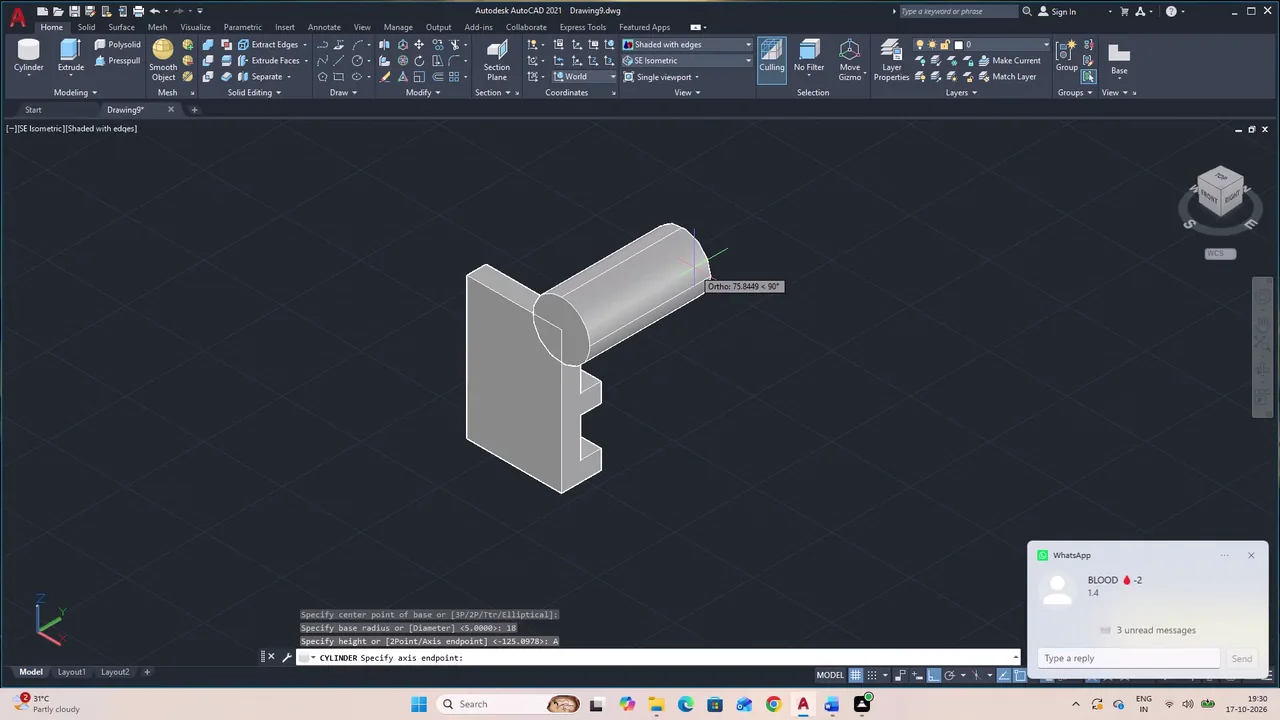
Build a 3D solid model of a split cylindrical housing bracket.
Create and refine a shaded 3D mechanical bracket in AutoCAD using boxes, cylinders, extrusions, Boolean operations, and positioning edits. Save it as “28 3DM,” generate and dimension projected drawing views in Layout1, then plot the layout to a PDF.
Task set
task.pdfThe task: statement, rubrics and every drawing sheet599 KB↗task_desc.jsonThe task as data: statement, input files and deliverables3 KB↗rubrics.jsonThe rubrics as data2 KB↗references.zipThe drawing sheets and close-ups the task works from573 KB↓gold.zipThe finished files: native and neutral exports67 KB↓