Model a crane hook block assembly with side plates and lock nuts
- Software
- SOLIDWORKS
- Platform
- Windows
- Length
- 1 h 37 min
- Resolution
- 1920 × 1080
- Output
- SLDASM, SLDPRT, STEP, X_T
Windows
Task
Build a crane hook block as a millimetre assembly of eleven part files, using the supplied dimensioned diagrams diagram_01.png to diagram_12.png and their detail images. Where a sheet and this brief disagree, follow the values below.
Parts and quantities (34 component instances):
1. Lifting hook, qty 1. A T-handle key with a Ø30 x 5 collar (R3 fillet), a Ø20 x 31 shaft, a Ø14 x 3 neck and a Ø16 x 16 pin with a Ø3 cross hole. The double-claw handle is 130 long overall and 96 across, with R25/R19/R12 claw radii and R6 handle fillets.
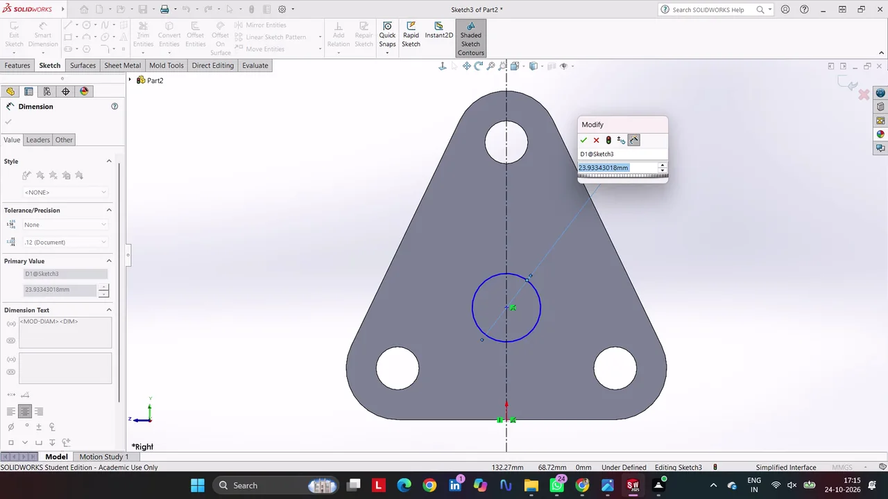
2. Triangular support plate, qty 2. Plate 5 thick, 115 profile height and 76 base. It has 3x Ø15 corner holes, a Ø25 central bore and 3x Ø6 holes on a Ø35 PCD.
3. Hook anchor body, qty 1. A block with Ø16 trunnions carrying Ø12 x 10 pins at both ends (mirrored), Ø38 seat bosses with Ø32 grooves, a Ø25 through bore and an R3 boss fillet.
4. End bush flange, qty 2. A revolved Ø51 x 12 flange with an R2 edge fillet, a Ø16 centre bore and 3x Ø6 holes on PCD 35.
5. Plate spacer, qty 3. A Ø22 x 46 body with Ø15 x 18 journals at both ends, 82 overall.
6. Flanged bush, qty 1. A Ø25 x 28 shank with a Ø30 x 3 flange and a Ø20 through bore.
7. Flat washer, qty 9. Ø30 OD, Ø17 bore, 3 thick.
8. Hex bolt M6 x 12, qty 6. A 9 AF x 3 head with a 0.5 x 0.5 head chamfer.
9. Slotted bushing (lock nut M16), qty 1. Ø30 x 15 with a Ø16 bore, a Ø3 cross hole, 4 axial slots and a 1x45° chamfer.
10. Slotted ring (lock nut M12), qty 2. Ø25 x 8 with a Ø12 bore, 4 spanner slots 4 wide x 2 deep and a 1x45° chamfer.
11. Slotted round nut (lock nut M15), qty 6. Ø27 x 7 with a Ø15 bore, 4 spanner slots 4 wide and a 1x45° chamfer.
Assembly layout:
- Mount the two support plates parallel, seated against the shoulders of the three spacers' Ø22 x 46 bodies, with the spacer journals passing through the corner holes.
- Secure each journal end with a washer and an M15 lock nut.
- Bolt the end bushes to the plate centre bores with the six M6 bolts.
- Carry the hook anchor between the plates on its trunnions.
- Pass the hook through the anchor and bush, retained by the M16 lock nut.
The overall envelope is approximately 90 x 178.5 x 111.98. Fix the hook as the base component and fully locate every other part with concentric, coincident and parallel mates, leaving no mate errors.
Modelling practice:
- Give every feature a descriptive name that states its size, for example "Bore Ø15" or "Spanner Slots 4x4mm".
- Use mirror features for symmetric journals, pins and grooves.
- Assign a steel material (Steel or Plain Carbon Steel) to each part.
- Fill in the Description, PartNo and Material custom properties on every part and on the assembly. The assembly is Crane_Hook_Assembly.
ReferenceSheet 1
1 of 12Loading the drawing
Rubrics17
- R1
The model shall be an assembly in millimetres containing 34 unsuppressed, resolved component instances drawn from 11 distinct part files.
- R2
The model shall contain 9 flat washer instances of Ø30 OD, Ø17 bore and 3 mm thickness.
- R3
The model shall contain 6 hex bolt instances with a Ø6 x 12 shank and a 9 AF x 3 mm head.
- R4
The model shall contain 6 slotted round nuts of Ø27 x 7 with a Ø15 bore and 4 spanner slots.
- R5
The model shall contain 3 plate spacers 82 mm overall, with a Ø22 x 46 body and Ø15 x 18 journals at both ends.
- R6
The model shall contain 2 triangular support plates 5 mm thick, each with 3x Ø15 corner holes, a Ø25 central bore and 3x Ø6 holes on a Ø35 PCD.
- R7
The model shall contain 2 end bush flanges of Ø51 x 12 with a Ø16 centre bore and 3x Ø6 holes on PCD 35.
- R8
The model shall contain 2 slotted rings of Ø25 x 8 with a Ø12 bore and 4 spanner slots.
- R9
The model shall contain a hook part with a Ø30 x 5 collar, a Ø20 shaft, a Ø16 pin and a Ø3 cross hole.
- R10
The model shall contain a hook anchor part with Ø16 trunnions, Ø12 pins, Ø38 seat bosses and a Ø25 through bore.
- R11
The model shall contain a flanged bush with a Ø25 x 28 shank, a Ø30 x 3 flange and a Ø20 through bore, and a Ø30 x 15 slotted bushing with a Ø16 bore.
- R12
The model shall have an overall assembled envelope of approximately 90 x 179 x 112 mm.
- R13
The model shall have the hook component fixed and all other components located by mates, with no mate in error.
- R14
The model shall use concentric, coincident and parallel mate types to position the components.
- R15
The model shall use descriptive, size-bearing feature names in the parts, such as "Bore Ø15" or "Journal Ø15x18", rather than default names.
- R16
The model shall use mirror features for the symmetric spacer journals and the anchor trunnion pins.
- R17
The model shall assign a steel material (Steel or Plain Carbon Steel) to every part and carry Description, PartNo and Material custom properties on each part and on the assembly.
Gold outputCrane_Hook_AssemblySLDASM, STEP, X_T
1 of 12Loading
Drag to turn, then scroll to zoom
Build a crane hook block as a millimetre assembly of eleven part files, using the supplied dimensioned diagrams diagram_01.png to diagram_12.png and their detail images.
Created numerous SOLIDWORKS parts with detailed sketches, extrusions, cuts, fillets, chamfers, patterns, appearances, and PDF exports, then assembled the components into an exploded Crane Hook Assembly. Applied and adjusted assembly mates while inspecting the mechanism from multiple views, saved the assembly as “Crane Hook Assembly,” and printed it to PDF.
Task set
task.pdfThe task: statement, rubrics and every drawing sheet9 MB↗task_desc.jsonThe task as data: statement, input files and deliverables14 KB↗rubrics.jsonThe rubrics as data3 KB↗references.zipThe drawing sheets and close-ups the task works from10 MB↓gold.zipThe finished files: native and neutral exports2 MB↓